Liquid applicator

a liquid applicator and liquid technology, applied in the field of liquid applicators, can solve the problems of contamination or deterioration of liquid content, inconvenient washing of liquid content remaining on the hand, and high viscosity liquid content not being smoothly discharged ou

Active Publication Date: 2015-11-17
ZEN DESIGN SOLUTIONS
View PDF8 Cites 2 Cited by
  • Summary
  • Abstract
  • Description
  • Claims
  • Application Information

AI Technical Summary

Benefits of technology

[0011]The present invention relates, in general, to a liquid applicator for cosmetics, chemicals or the like, and, more particularly, to a liquid applicator comprising a container, an application member and an actuation means which when actuated enables a user to directly apply liquid content from the container onto a desired portion of user's skin. Further, the liquid applicator of present invention prevents contamination of the liquid content from a biasing member of the liquid applicator.
[0026]According to an embodiment of the invention, to bring the liquid applicator to the open position, the cap is displaced axially in an upward direction so that the upward biasing force of the biasing member displaces the collar holder and the flow control unit axially in the upward direction along the longitudinal axis of the liquid applicator. Preferably, the cap is screwed off to bring the liquid applicator to an open position. As the cap is screwed off the biasing force of the biasing member pushes the flow control unit in an upward direction to open the apertures in the bottom wall of the plug and simultaneously the flow control unit pushes the collar holder so that the collar holder moves in an upward direction. In the open position, a bottom end of the annular groove of the collar holder abuts against the annular projection on the inner side of the peripheral wall of the plug and the inner side at the bottom end of the peripheral wall of the cylindrical portion of the flow control unit abuts against the radially extended circular rim of the post on the bottom wall of the plug. In the open position of the liquid applicator, the apertures in the bottom wall of the plug are completely open by the flow control unit and the liquid content flows from the apertures to the discharge barrel following a path through the plug and the collar holder such that the container, the plug and the collar holder are in fluid communication with each other. No liquid content enters into the flow control unit and the biasing member disposed inside the flow control unit does not come into contact with the liquid content. Thus, the liquid applicator prevents the liquid content from getting contaminated and also prevents wear of the biasing member, extending the life of the biasing member. Further, in the open position, when the main body is squeezed to force the liquid content out, no squeezed liquid content will backflow even when the pressure is reduced or stopped. Thus, the liquid applicator can not only be used conveniently but can isolate air pollution and, thus, has advantage in usage.

Problems solved by technology

Such a container is used by squeezing a container body or spraying contents, because the liquid content having high viscosity is not smoothly discharged out of the container although the container is stood upside down or shaken.
However, the conventional tube-type or pump-type container is problematic in that, when a user desires to use the liquid content contained in the container, he or she must discharge the content through an outlet portion of the container and then apply the content onto his or her body part using the hand, so that it is inconvenient to wash off the content remaining on the hand after the liquid content has been applied to the body part.
Since, the biasing member is generally made from a material including metal; there are chances of liquid content reacting with the material of the biasing member, resulting in contamination or deterioration of the liquid content.

Method used


Image

  • Liquid applicator
  • Liquid applicator
  • Liquid applicator

Examples


Embodiment Construction

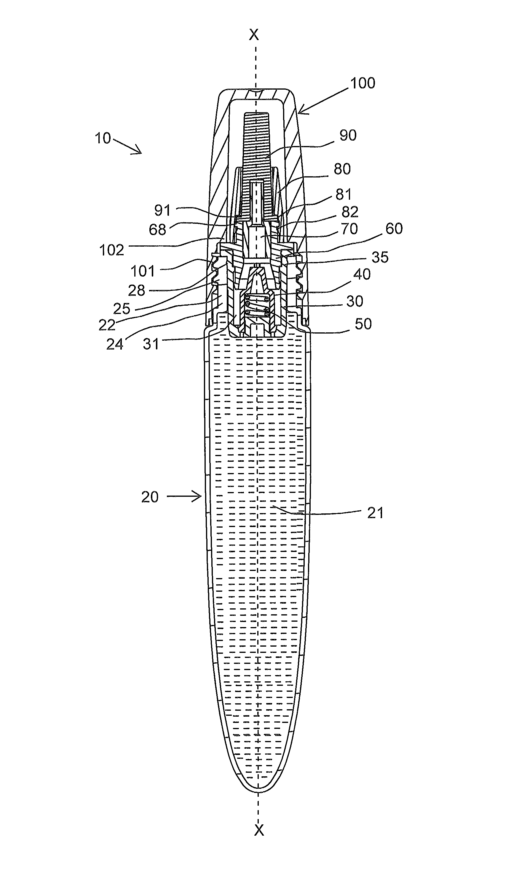
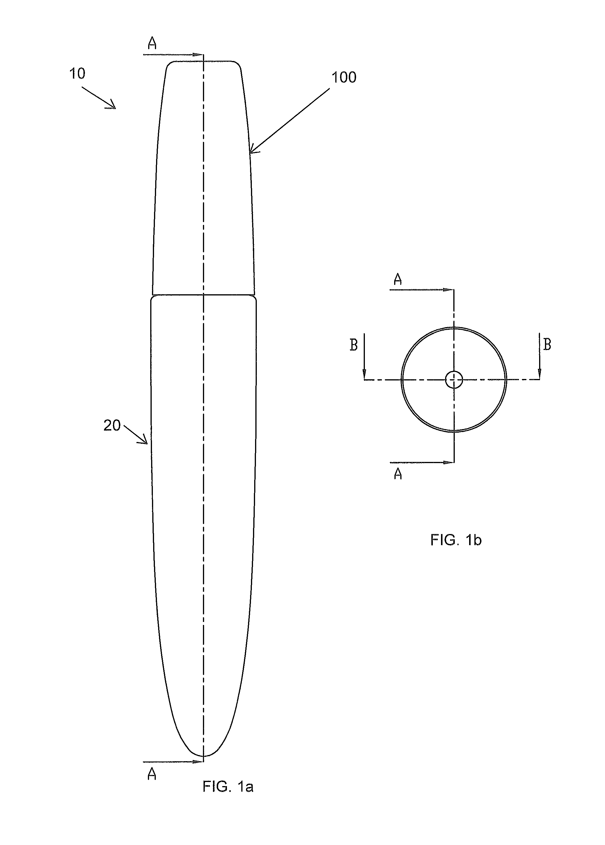
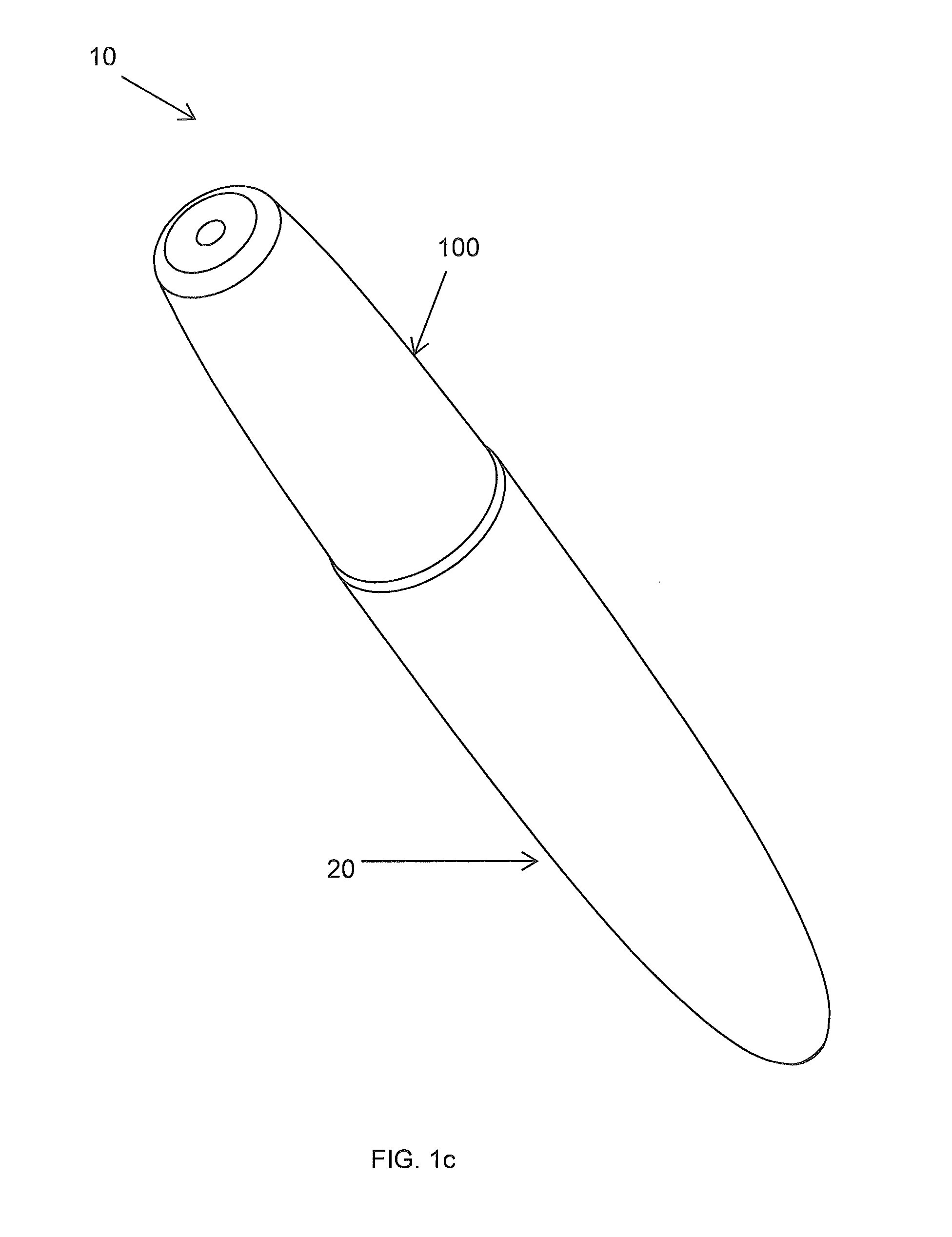
[0056]FIG. 1a to 2 shows a liquid applicator 10 according one embodiment of the present invention. FIG. 1a and FIG. 1b show a front view and a top view of the liquid applicator 10 in a closed position. FIG. 1c shows a perspective view of the liquid applicator 10.

[0057]As represented in FIGS. 1a to 2, the liquid applicator 10 has a container 20 which stores therein, as liquid content 21 (as shown in FIG. 6a), cosmetics such as lip cream, lip color, chemicals or the like, and is used as a tool for application of cosmetics, chemicals or the like, and incorporates, in addition to the container 20, a plug 30, a flow control unit 40, a biasing member 50, a collar holder 60, a discharge barrel 70, a collar 80, an application member 90 and an actuation means in form of a cap 100 which will be explained later.

[0058]The container 20 is a tube container having a mouth portion 22 and a main body 23 which can be deformed by being pressed. According to another embodiment of the invention, the con...


PUM


Abstract

A liquid applicator comprising a container, a plug, a flow control unit, a biasing member, a collar holder, a discharge barrel, a collar, an application member, a cap and optionally a jacket. The cap or the jacket is configured to displace the collar holder along a longitudinal axis of the liquid applicator to bring the liquid applicator to an open position or to a closed position. The flow control unit closes the at least one aperture in the plug in the closed position; and in the open position, the flow control unit opens the at least one aperture in the plug and the liquid content flows from the at least one aperture to the collar holder so that the container, the plug and the collar holder are in fluid communication with each other.

Description

BACKGROUND[0001]1. Field of the Invention[0002]The present invention relates, in general, to a liquid applicator for cosmetics, chemicals or the like, and, more particularly, to a liquid applicator comprising a container, an application member and an actuation means, which when actuated enables a user to directly apply liquid content from the container onto a desired portion of user's skin.[0003]2. Description of the Related Art[0004]Generally, various kinds of cosmetics are available in the market. Recently, for the convenience of users, cosmetics are changing from solid cosmetics into liquid cosmetics. Furthermore, in order to allow a user to conveniently store and use the liquid cosmetics, various types of liquid applicators are being developed and used.[0005]Further, various liquid applicators comprising containers for containing cosmetics, such as creams or lotions, which are applied to a user's body part, medicines such as ointments, and various kinds of liquid or liquid mater...

Claims


Application Information

Patent Timeline
Patent Type & Authority Patents(United States)
IPC IPC(8): B43K5/00A45D34/04
CPCA45D34/042
Inventor PIRES, LEO CLIFFORDHWANG, ROGERBOSE, RAHULDESWAL, RAJESH
Owner ZEN DESIGN SOLUTIONS
Why Eureka
Try Eureka