Half thrust bearing and bearing device

a technology of bearings and thrust reliefs, which is applied in the direction of crankshaft bearings, sliding contact bearings, mechanical equipment, etc., can solve the problems of easy damage (seizure), difficult to prevent the slide surface in close proximity of the thrust relief on the rear side in the rotational direction of the crankshaft, and the tendency of crankshaft vibration to become large, etc., to reduce the weight of internal combustion engines, reduce the shaft diameter of crankshafts, and reduce rigidity

Active Publication Date: 2015-11-17
DAIDO METAL CO LTD
View PDF10 Cites 18 Cited by
  • Summary
  • Abstract
  • Description
  • Claims
  • Application Information

AI Technical Summary

Benefits of technology

[0010]In recent years, in order to reduce weights of internal combustion engines, shaft diameters of crankshafts have been reduced, and the crankshafts have become lower in rigidity than conventional crankshafts. Therefore, deflection has easily occurred in the crankshafts at the time of operation of the internal combustion engines, and vibration of the crankshafts has tended to become large. Accordingly, the slide surfaces of the half thrust bearings and thrust collar surfaces of the crankshafts tends to be in direct contact with each other, and damage (seizure) is easily occurred.

Problems solved by technology

Therefore, deflection has easily occurred in the crankshafts at the time of operation of the internal combustion engines, and vibration of the crankshafts has tended to become large.
Accordingly, the slide surfaces of the half thrust bearings and thrust collar surfaces of the crankshafts tends to be in direct contact with each other, and damage (seizure) is easily occurred.
However, even if the art of JP-A-2001-323928 is adopted, it is especially difficult to prevent the slide surface in close vicinity of the thrust relief on the rear side in the crankshaft rotational direction of the half thrust bearing from contacting the thrust collar of the crankshaft a long as the vibration due to deflection of the crankshaft described above is large.
Therefore, there is the possibility of occurrence of seizure on the slide surface of the half thrust bearing.

Method used


Image

  • Half thrust bearing and bearing device
  • Half thrust bearing and bearing device
  • Half thrust bearing and bearing device

Examples


embodiment 1

Entire Configuration of Bearing Device

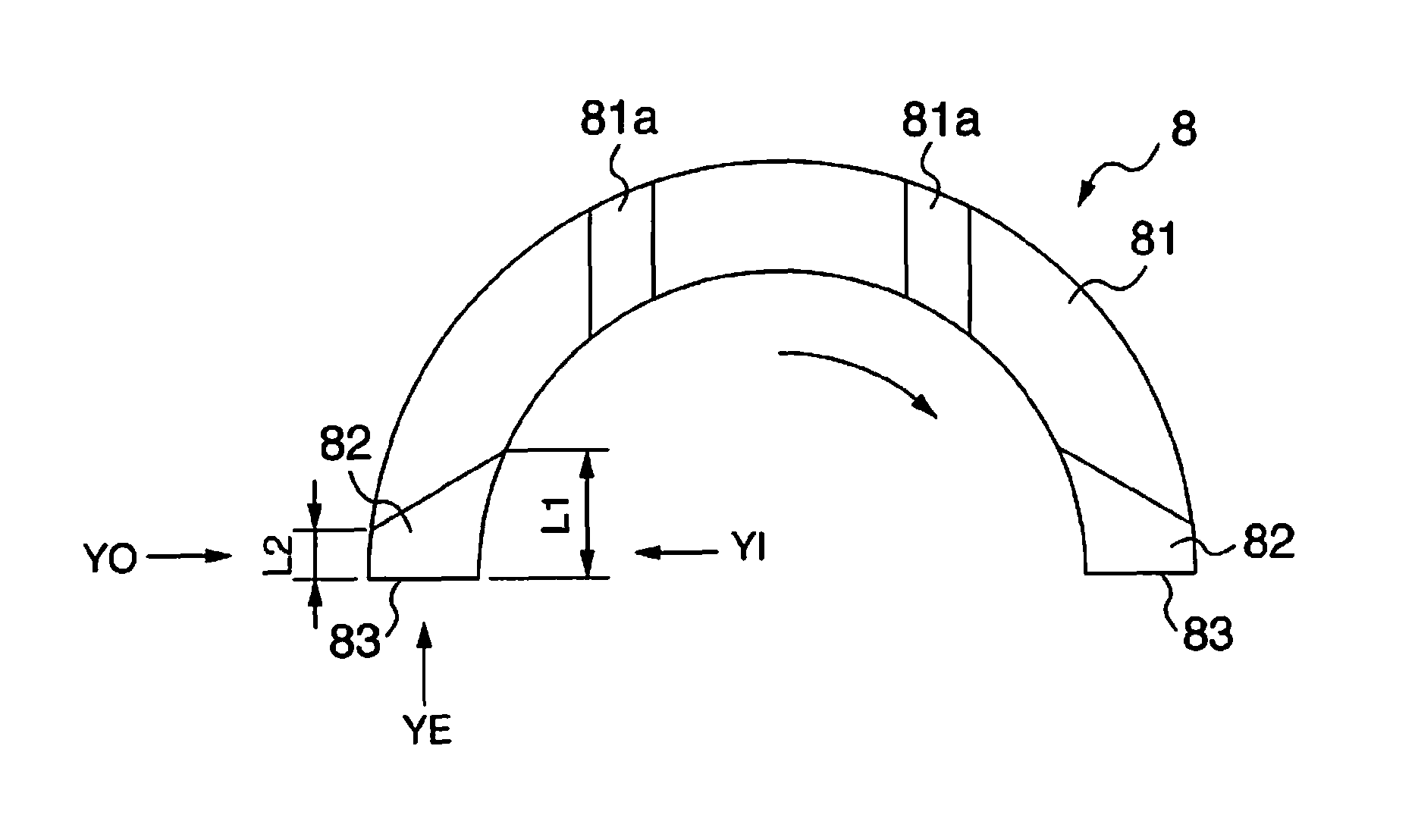
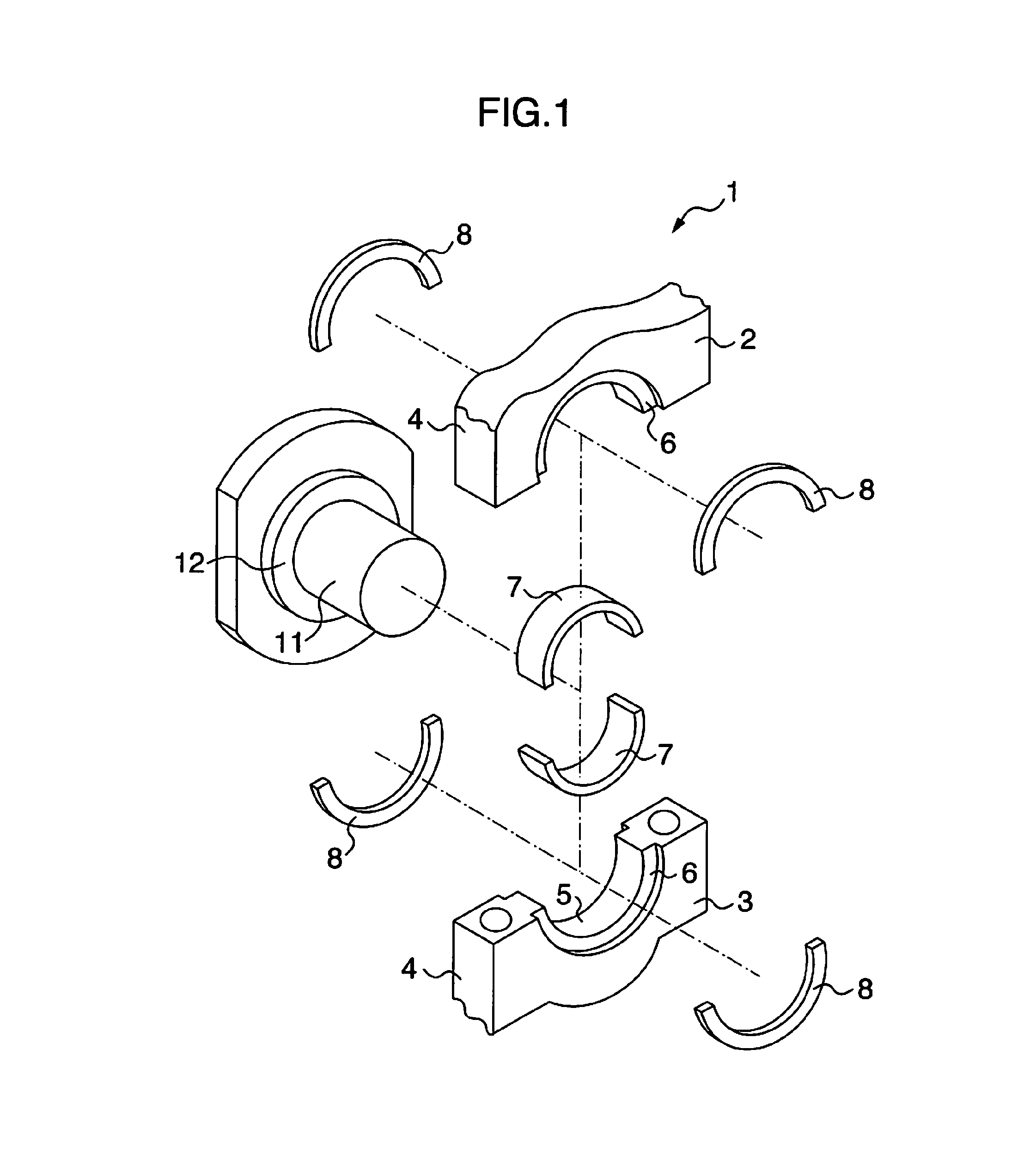
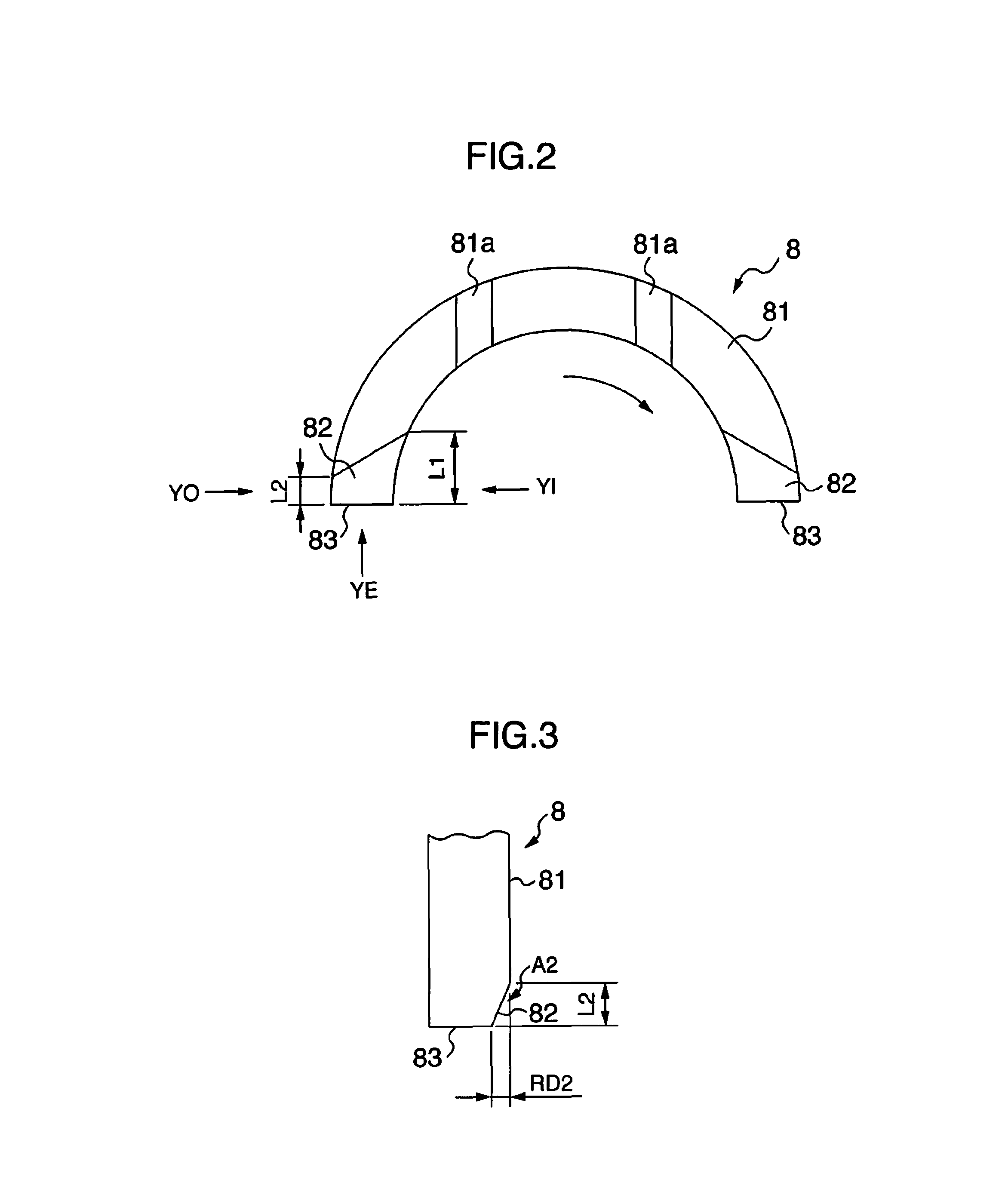
[0040]First, with use of FIGS. 1, 6 and 7, an entire configuration of a bearing device 1 including a half thrust bearing 8 of the present invention will be described. As shown in FIGS. 1, 6 and 7, in a bearing housing 4 that is configured by attaching a bearing cap 3 to a lower portion of a cylinder block 2, a bearing hole 5 that is a circular hole that penetrates through both side surfaces is formed, and at an circumferential edge of the bearing hole 5 in the side surface, receiving seats 6 and 6 that are concave portions in a circular ring shape are formed. Half bearings 7 and 7 that rotatably bear a journal portion 11 of a crankshaft are combined into a cylindrical shape and are fitted in the bearing hole 5. Half thrust bearings 8 and 8 that receive an axial force f (see FIG. 7) via a thrust collar 12 of the crankshaft are combined into a circular ring shape and fitted in the receiving seats 6 and 6.

[0041]As shown in FIG. 6, a lubricating oil...

embodiment 2

[0072]Hereinafter, with use of FIGS. 8 and 9, a half thrust bearing 8A including the thrust relief 82 of a different mode from that of embodiment 1 will be described. Note that explanation of the same or equivalent portions as the contents described in the aforementioned embodiment will be made by assigning the same reference signs thereto.

(Configuration)

[0073]First, a configuration will be described. The entire configuration of the bearing device 1 of the present embodiment is similar to that of embodiment 1. A configuration of the half thrust bearing 8A is also substantially similar to embodiment 1 except for the shapes of the thrust reliefs 82 and 82.

[0074]However, the thrust relief 82 of the half thrust bearing 8A of the present embodiment is configured by a curved surface, as shown in FIGS. 8 and 9. The curved surface is formed so that the thrust relief clearance becomes larger than the flat surface described in embodiment 1. In other words, the curved surface is recessed into ...

embodiment 3

[0078]Hereinafter, with use of FIGS. 10 to 13, half thrust bearings 8B and 8C that include the thrust relief 82 in a different mode from those of embodiments 1 and 2 will be described. Note that explanation of the same or equivalent portions as the contents described in the aforementioned embodiments will be made by assigning the same reference signs thereto.

(Configuration)

[0079]First, a configuration will be described. An entire configuration of the bearing device 1 of the present embodiment is similar to that of embodiment 1. A configuration of the half thrust bearing 8B is substantially similar to that of embodiment 1 except for the shapes of the thrust reliefs 82 and 82.

[0080]However, in the half thrust bearing 8B of the present embodiment, in the thrust relief 82 on a rear side in the rotational direction of the crankshaft or each of both thrust reliefs 82 and 82, a length L3 of the thrust relief in a predetermined position between an inner end portion and an outer end portion ...


PUM


Abstract

A half thrust bearing having a semicircular ring shape for receiving an axial force of a crankshaft of an internal combustion engine is provided. The half thrust bearing includes thrust reliefs formed adjacently to end surfaces on both sides in a circumferential direction on a slide surface side which receives the axial force so that wall thicknesses become thinner toward the end surfaces. The thrust relief on a rear side in a rotational direction of the crankshaft or both thrust reliefs are formed so that a length of the thrust relief in an inner end portion in a radial direction of the half thrust bearing is longer than a length of the thrust relief in an outer end portion in the radial direction of the half thrust bearing.

Description

BACKGROUND OF THE INVENTION[0001]1. Field of the Invention[0002]The present invention relates to a thrust bearing and a bearing device that receive an axial force of a crankshaft of an internal combustion engine.[0003]2. Description of the Related Art[0004]The crankshaft of an internal combustion engine is rotatably supported, at a journal portion thereof, in a cylinder block lower portion of the internal combustion engine via a main bearing that is configured by combining a pair of half bearings in a cylindrical shape.[0005]One or both of a pair of half bearings are used in combination with a half thrust bearing that receives a force in the axial direction of the crankshaft. The half thrust bearing is placed on at least one of both end surfaces of the half bearings in the axial direction.[0006]The half thrust bearing receives the force in the axial direction that occurs in the axial direction of the crankshaft. Namely, the half thrust bearings are disposed for the purpose of bearin...

Claims


Application Information

Patent Timeline
Patent Type & Authority Patents(United States)
IPC IPC(8): F16C9/02F16C17/04F16C33/04
CPCF16C33/046F16C9/02F16C17/04F16C33/1075F16C2360/22
Inventor TANAKA, SHIHOOZAWA, YOSHIHIROMAITANI, SHINYAYAMAMOTO, TAKEHARU
Owner DAIDO METAL CO LTD
Why Eureka
Try Eureka