Fan array control system

a control system and fan array technology, applied in space heating and ventilation control systems, lighting and heating apparatus, heating types, etc., can solve the problems of fan failure, fan replacement, and inability to achieve the average useful life of the fan, and achieve the effect of prolonging the useful life of the ventilation fan system

Active Publication Date: 2015-11-17
DIGITAL CONTROL SYST
View PDF23 Cites 22 Cited by
  • Summary
  • Abstract
  • Description
  • Claims
  • Application Information

AI Technical Summary

Benefits of technology

[0023]In accordance with a first aspect of the invention, a ventilation fan system is provided that is adapted for responding to an external device making requests for required changes in ventilation and in accordance with enhancement of mean-time-between-failure of the system. The system comprises: a plurality of ventilation fans and a fan array controller operatively interconnected by a network to the plurality of ventilation fans. The fan array controller is adapted for sending and receiving signals to and from each of the ventilation fans over the network, and the fan array controller is further adapted for receiving requests and sending status to and from the external device. The system further comprises means for communicating between the plurality of ventilation fans and the fan array controller, wherein each of the ventilation fans is adapted for selectively responding to control and data requests received from the fan array controller, and wherein the fan array controller deploys the plurality of ventilation fans in accordance with data received from the plurality of ventilation fans and the external device to lengthen the useful life of the ventilation fan system.

Problems solved by technology

If a particular system design requires fan usage in excess of the specified duty cycle for the fan, full useful life of the fan would not be achieved on average.
After a fan has run for the rated time according to its MTBF, failure may be anticipated and the fan may be replaced prior to failure during scheduled maintenance of the system.
The replacement and repair of individual fans may in some cases be inconvenient, and especially so where the fans are not readily accessible, such as on a highly pitched rooftop or inside of a computer system that must be turned off in order to access the fans.
A downside to this approach is the higher up-front expense of installing and replacing such a system.
However, prior art fan array systems have paid little or no heed to MTBF and duty cycle considerations in fan arrays.
An array of fans may be fully redundant, partially redundant or not redundant at all.
More importantly, increase of lifespan of such fully redundant switched arrays beyond that normally expected by increasing the redundancy of fans in the array, has not occurred with and has not been a stated goal of such prior art fan arrays.
Absent volume purchasing and installation cost savings, such a system would have cost three times as much in terms of fan costs and installation as a single fan system, and the life of the array may have been expected to have lasted approximately three times as long as a single fan.
Thus, though using such an array has been more convenient than a single fan from a maintenance and repair perspective, there has been no appreciable additional cost savings or enhancement of the life of the array beyond the sum of the MTBFs of each fan in the array.
Thus, for example, where two full duty cycle fans at capacity are needed to meet demands, and serial switching is employed, 3× redundancy would assume a system with six fans, and so on, and the same limitations on cost savings and enhanced system MTBF would apply.
While in such a case greater performance effectiveness and perhaps efficiencies have been accomplished by implementing an array, such a prior art array has not been employed so as to have enhanced the overall MTBF of the system beyond the rated MTBF of one of the fans of the system.
Further, such partially redundant fan arrays have incorporated application of remaining fan power upon encountering a failed fan in the system, similar to the serially-switched, completely redundant systems described above.
As may be appreciated from the foregoing description, partially redundant systems have presented a more complicated scenario for considering system MTBF and duty cycle, since each such partially redundant fan array system has presented widely diverging and unique capabilities to meet widely varying demands.
Thus, there has been lacking in the prior art a fan array system that has the intelligence for making determinations about which fans to use based upon demand, static fan data, such as rated MTBF, duty cycle and rated power consumption, rated temperature and rated speed, and dynamic fan data, such as hours in use, actual power consumption, revolutions per minute, and calculated remaining life, to enhance the MTBF of a fan system.
Further, prior art systems have not allowed for inclusion of fans having differing MTBFs or other characteristics in a single array in a way that determines use based upon fan capability in order to enhance overall MTBF.

Method used


Image

  • Fan array control system
  • Fan array control system
  • Fan array control system

Examples


Embodiment Construction

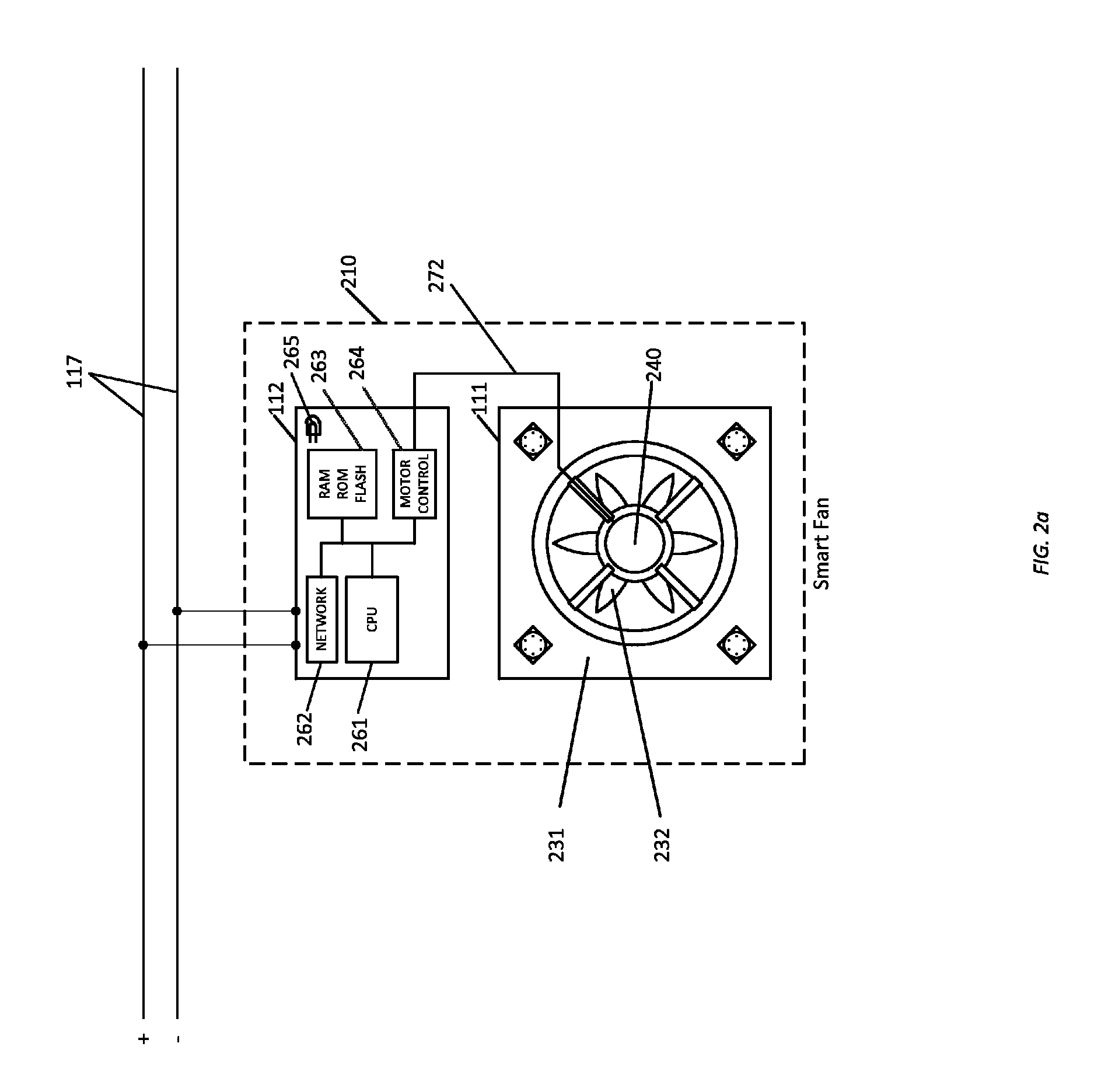
Smart Fan Array and Array Controller Embodiment

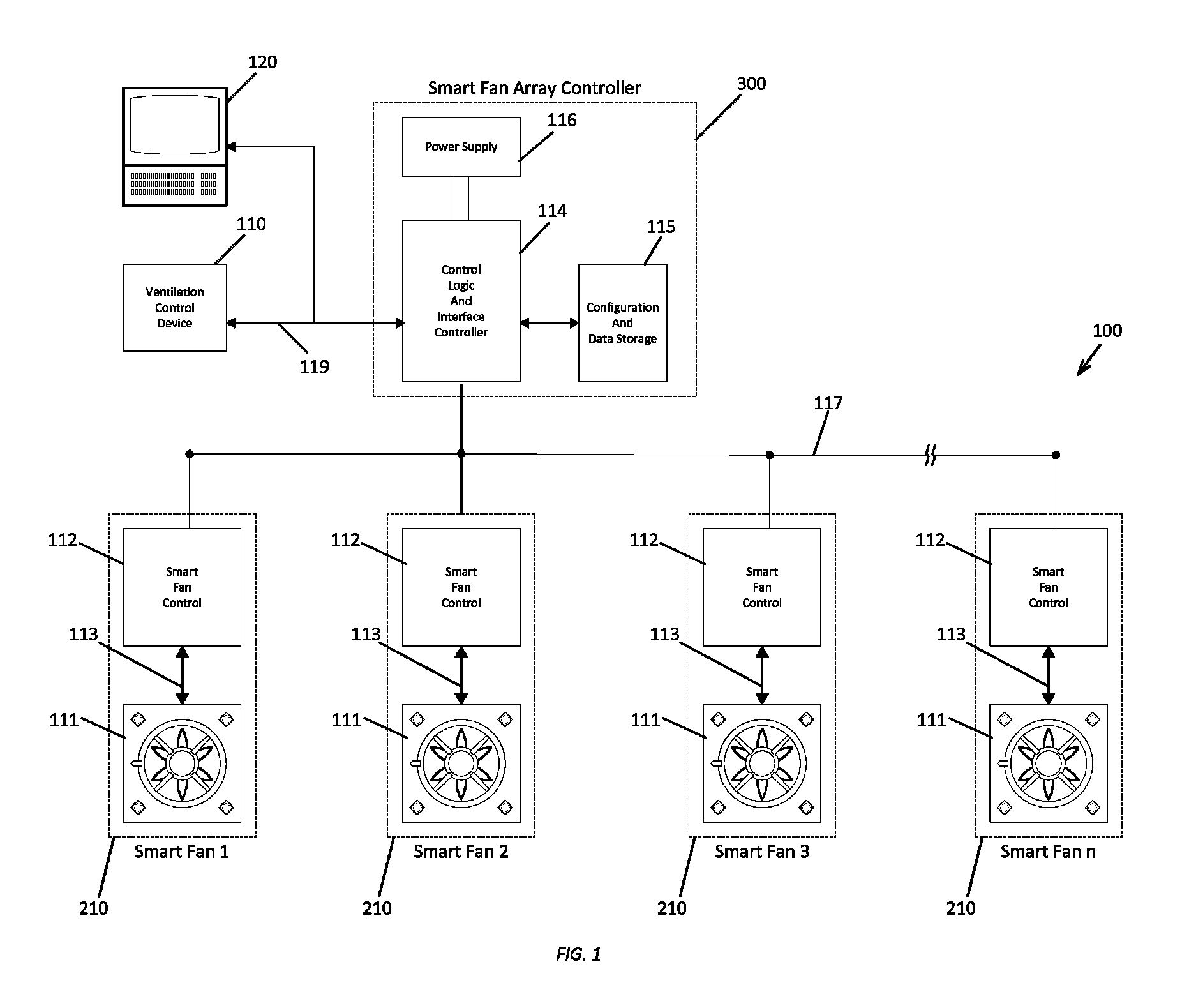
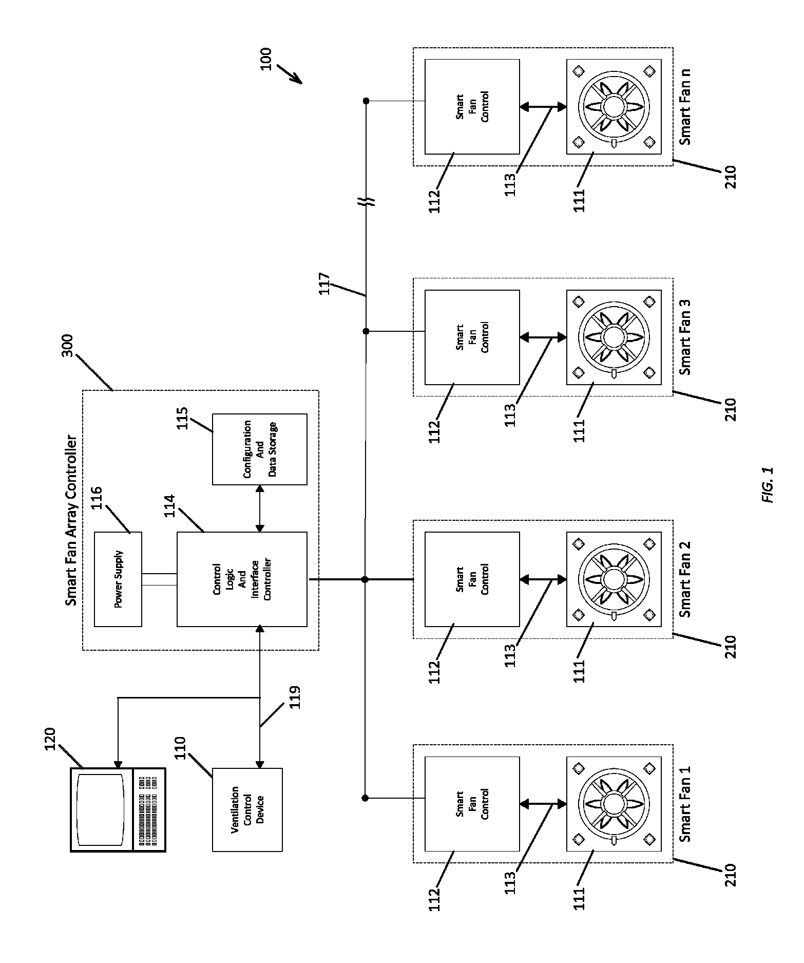
[0055]Referring to FIG. 1, there is shown a first embodiment of a smart fan array system comprising a smart fan array 100 connected over a local operating network 117 to a smart fan array controller 300.

[0056]Commands for controlling the smart fan array system are primarily received from an external ventilation control device 110 networked via network 119 to the controller 300. Optionally, a computer 120 also may be networked via network 119 for purposes of ventilation control, programming, configuring and initialization of the system. The external ventilation controller 110 may consist of a simple thermostat, or of a more complex processor 120, which determines and conveys ventilation requirements for a target environment, and is designed to send commands to the smart fan array controller 300 to meet such ventilation requirements. Preferably, the external ventilation controller 110 is capable of requesting the following: added ventilat...


PUM


Abstract

A system and method for intelligent management of an array of fans. The system uses mean-time-between-failure, fan usage and other data in add ventilation, subtract ventilation and recycle array routines to maximize the life of the fans and the array. The system comprises a primary embodiment making use of smart fans in the array, each smart fan including a fan and appropriate control electronics capable of processing commands received from a smart fan array controller. Fan control signals are multiplexed over a local operating network power line using carrier communication protocols, command messages and data values, all to accomplish a goal of the system to maximize fan life. In an alternate embodiment, fan and array control electronics are integrated onto the fan array controller itself and power is provided to conventional fans using a conventional wiring harness.

Description

FIELD OF INVENTION[0001]The invention relates generally to fans and fan arrays, and more specifically to fans and fan arrays having control systems that enable automated operation of one or more fans in the array in a way that conserves energy and increases the anticipated lifetime of the array over prior art fan arrays.BACKGROUNDMean-Time-Between-Failure (MTBF) and Duty Cycle for Fans[0002]Fans, or blowers, are used to move air in a desired direction. Such fans can be used in a variety of applications, including but not limited to ventilating and cooling an area such as attic space, protecting components from overheating such as in a desktop, or larger, computer housing, evacuating humid or moist air such as in a bathroom after a shower, or evacuating hazardous gases or smoke from an area in a fire protection or other environmental control system.[0003]Such fans are rated by a manufacturer specification of mean-time-between-failure (MTBF) designating the number of hours that the fa...

Claims


Application Information

Patent Timeline
Patent Type & Authority Patents(United States)
IPC IPC(8): F24F11/00
CPCF24F11/0001F24F2011/0063F24F11/77F24F11/64Y02B30/70
Inventor ALLEN, DONKAMANI, JAYLE, PHUONGCORNELIUS, JACK
Owner DIGITAL CONTROL SYST
Why Eureka
Try Eureka