Eureka AIR delivers breakthrough ideas for toughest innovation challenges, trusted by R&D personnel around the world.

Interferometer

a technology of interferometer and polarizer, which is applied in the field of interferometer, can solve the problems of inaccurate guidance, low modulation of distance-dependent interference signals, and possible error in periodic signals,

Active Publication Date: 2015-11-17
DR JOHANNES HEIDENHAIN GMBH
View PDF11 Cites 2 Cited by
  • Summary
  • Abstract
  • Description
  • Claims
  • Application Information

AI Technical Summary

Benefits of technology

The present invention provides an interferometer that minimizes errors caused by cyclic signals and ensures that the resulting spot pattern is as invariant as possible with respect to displacements of the measuring reflector along axes which do not coincide with the measuring direction. This is achieved by constructing the measuring reflector in a flexible way that allows for a desired spot pattern to be adjusted while avoiding the need for expensive and heavy mirror arrangements. The technical effects of the invention include minimization of errors, improved accuracy of position measurement, and reduced size and weight of the interferometer.

Problems solved by technology

Such periodic signal errors may be caused, for example, by non-perfect polarization-optical elements, or else by other optical elements in the paths of the measurement and reference beams.
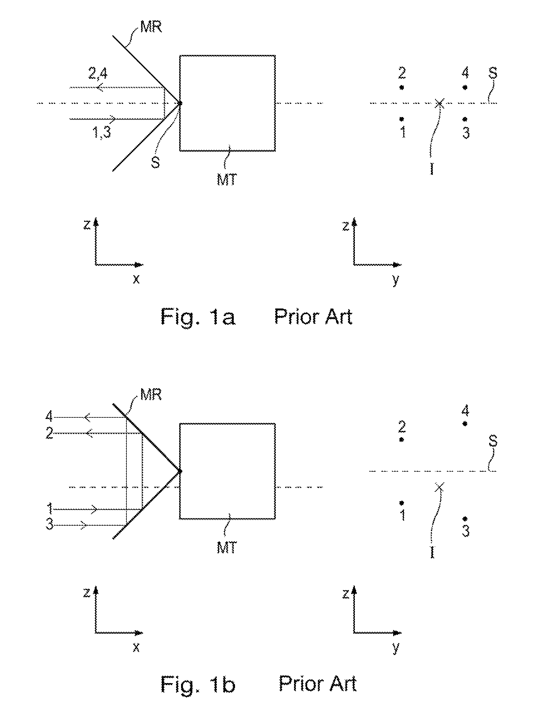
When working with a form of the measuring reflector having two plane mirrors oriented perpendicularly relative to each other, problems result in the case of a displacement of the measuring reflector along a direction which is oriented orthogonally relative to the measuring direction.
For example, this may be caused by inaccurate guidance.
Otherwise, the degree of modulation of the distance-dependent interference signals would be too low.
Unevenness of these components then causes errors in the position measurement.
Such a mirror arrangement requires high expenditure for alignment during assembly.
In addition, such a construction of the measuring reflector results in markedly increased weight on the part of the moving machine part.
This is not possible, for instance, in the case of a measuring reflector in the form of a roof prism.

Method used


Image

  • Interferometer
  • Interferometer
  • Interferometer

Examples


Embodiment Construction

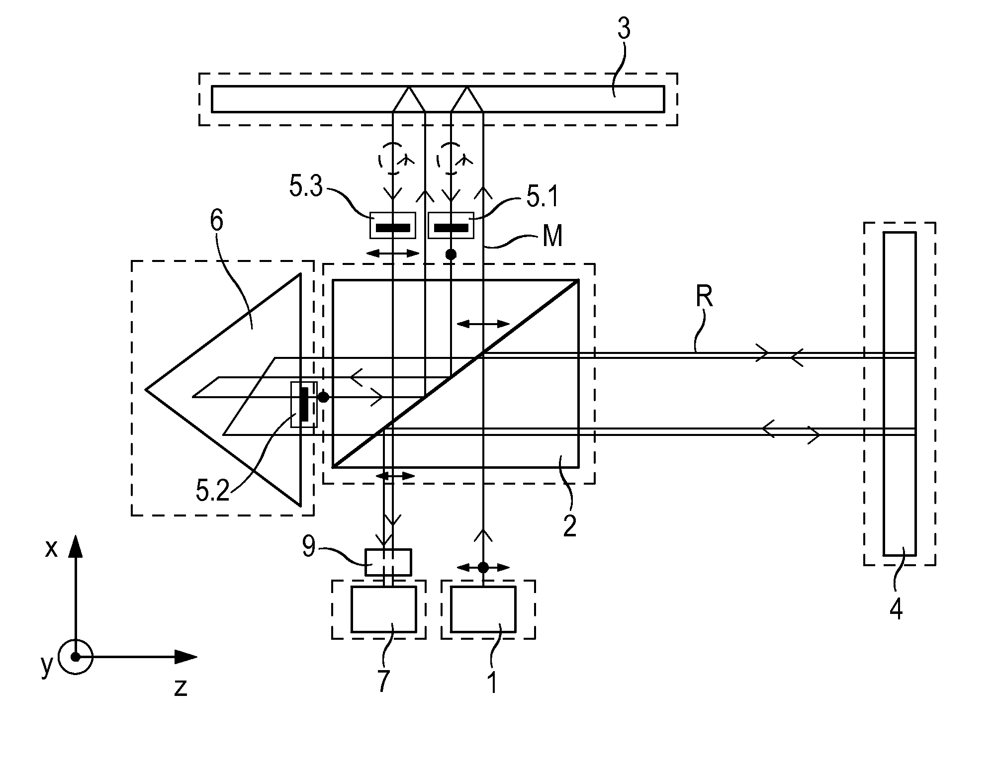
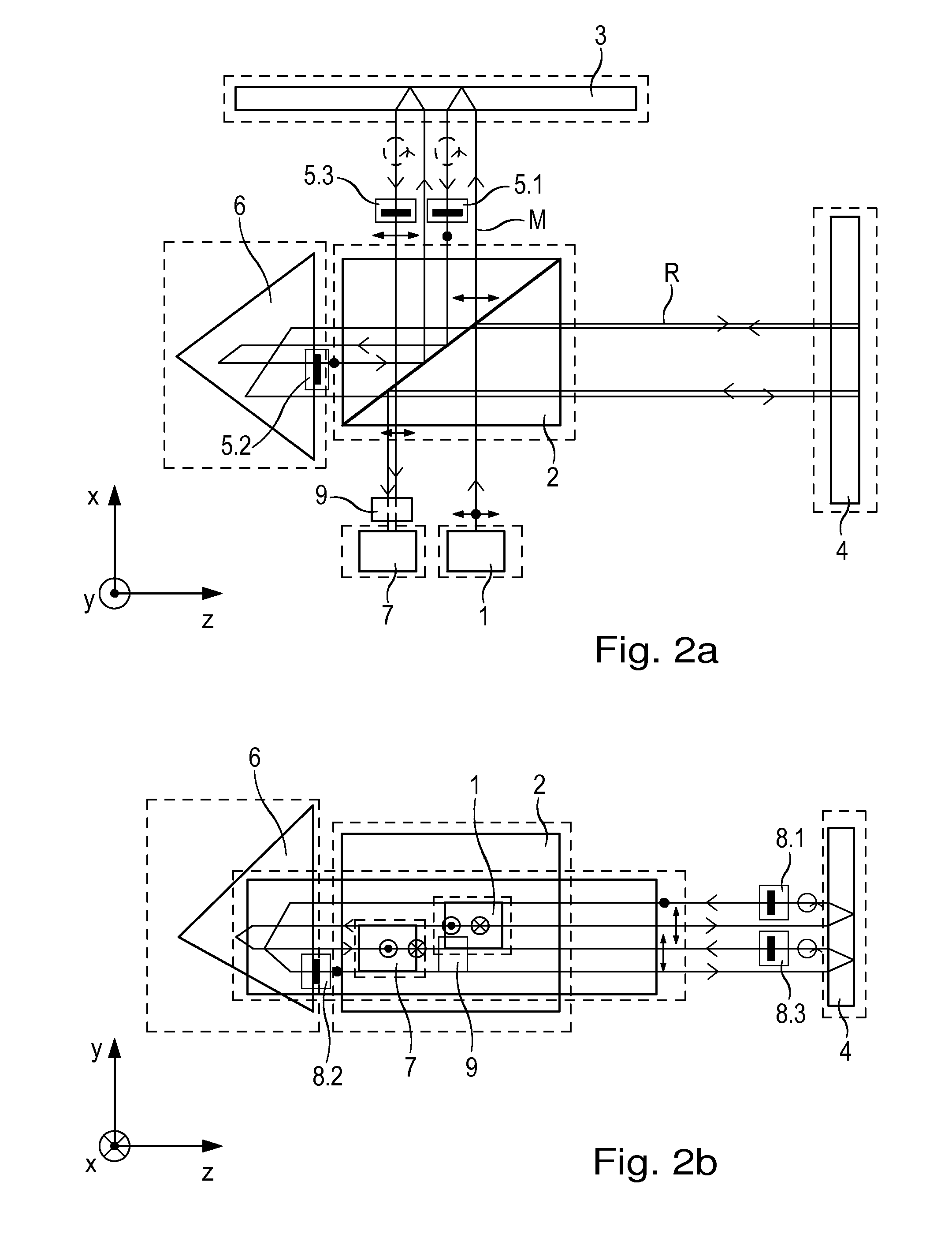
[0039]An interferometer according to an exemplary embodiment of the present invention is explained with reference to FIGS. 2a to 2c. These figures show various views of the beam path used for the signal generation. It is pointed out that for reasons of better clarity, not all components of the interferometer are illustrated in all views. Thus, certain polarization-optical elements 5.1 to 5.3 are illustrated only in FIG. 2a, for example, and other polarization-optical elements 8.1 to 8.3 are illustrated only in FIG. 2b. These polarization-optical elements 5.1 to 5.3, 8.1 to 8.3 are omitted completely in FIG. 2c. Likewise for reasons of clarity, the various polarization states of measuring beam M are shown only in FIG. 2a, the polarization states of reference beam R only in FIG. 2b, while they are omitted in FIG. 2c.

[0040]The interferometer includes a light source 1 which emits a linearly polarized beam of rays in the direction of a beam splitter 2. Preferably, a coherent laser light...


PUM


Abstract

An interferometer includes a light source and a beam splitter, via which the beam of rays emitted by the light source is split into a measurement beam and a reference beam. The measurement beam propagates in a measuring arm extending in a first direction between the beam splitter and a measuring reflector. The measuring reflector brings about an offset perpendicular to the direction of incidence between the measurement beam falling on it and the measurement beam reflected back by it. In a reference arm extending in a second direction, the reference beam propagates between the beam splitter and a reference reflector. In addition, the interferometer has a detector system, to which the superposed and recombined measurement beam and reference beam are able to be supplied, and via which a distance-dependent interference signal with respect to the position of the measuring reflector is able to be generated. The measuring reflector in each case includes at least one transmission grating as well as a reflector element.

Description

CROSS-REFERENCE TO RELATED APPLICATIONS[0001]The present application claims priority to Application No. 10 2012 223 887.5, filed in the Federal Republic of Germany on Dec. 20, 2012, and to Application No. 10 2013 201 611.5, filed in the Federal Republic of Germany on Jan. 31, 2013, each of which is expressly incorporated herein in its entirety by reference thereto.[0002]The present application also claims the benefit of U.S. Provisional Patent Application No. 61 / 739,883, filed on Dec. 20, 2012, which is expressly incorporated herein in its entirety by reference thereto.FIELD OF THE INVENTION[0003]The present invention relates to an interferometer.BACKGROUND INFORMATION[0004]U.S. Pat. No. 6,208,424, for example, describes an interferometer having a light source that emits a beam of rays in the direction of a beam splitter. The beam splitter splits the beam of rays into a measurement beam and a reference beam. The measurement beam then propagates in a measuring arm extending in a firs...

Claims


Application Information

Patent Timeline
Patent Type & Authority Patents(United States)
IPC IPC(8): G01B9/02
CPCG01B9/02059G01B9/02018
Inventor HOLZAPFEL, WOLFGANGDRESCHER, JOERGMEISSNER, MARKUSJOERGER, RALPHMUSCH, BERNHARDSPANNER, ERWINKAELBERER, THOMAS
Owner DR JOHANNES HEIDENHAIN GMBH
Why Eureka
Eureka Blog
Learn More