Paramagnetic Gas Sensor Apparatus and Adjustment Method

a gas sensor and paramagnetic gas technology, applied in magnetic measurement, analogue computers, analogue and hybrid computing, etc., can solve the problems of not being corrosion resistant, limiting compact electronic design, and not matching the sensitivity achieved by havens, so as to minimize the effect of momentum, reduce or minimize flow-dependent imbalances, and mitigate unbalanced flow

Active Publication Date: 2012-08-09
SERVOMEX GRP LTD
View PDF4 Cites 14 Cited by
  • Summary
  • Abstract
  • Description
  • Claims
  • Application Information

AI Technical Summary

Benefits of technology

[0019]The at least one flow balance element can be arranged to correct or mitigate a pressure imbalance in the vicinity of the test body and / or to correct or mitigate any flow-generated net torque on the test body due to the residual inherent asymmetry of the apparatus. The presence of the flow balance element achieves a reduction in flow dependence compared to an identical device without a flow balance element. The gas inlet means are arranged to supply gas to the chamber from at least two positions at opposite sides of the chamber. Gas flow from each of the positions will preferably be parallel to the direction of the magnetic field but flowing in opposed directions in order to minimise errors resulting from gas flow upon the test body.
[0020]The apparatus according to this aspect of the invention differs from prior art in that a flow balancing element (or elements) is used in order to balance the pressure drops across the test body from the differing flow paths around the test body. The inventors of the present invention have determined that an unbalanced fluid flow or pressure imbalance can be problematic, even after all practical measures have been taken to ensure that the internal volume of the device is essentially symmetrical and that the test body is suitably shielded from flow momentum impact. This flow balancing element (or elements) allows tuning of the system to minimise net flow effects on the suspension test body and also allows the use of flow paths around the test body (e.g. around each of two glass spheres filled with diamagnetic gas) that are only similar rather than absolutely identical symmetrical flow paths. This has advantages of improved flow error performance due to limitations of manufacturing tolerances or even allows deliberate design of asymmetrical geometry and reduced shielding of the test body, whether for cost reduction, for mechanically advantageous reasons or for any other reasons, to be implemented without detracting from the flow performance. For instance, a more aggressive flow regime can be pursued incorporating features such as bypass channels to improve flushing of the internal volume. Since the pressure drops in the flow regime in the vicinity of the test body are balanced by the flow balance element, there is a very effective net cancellation of any flow induced uncertainties. This is in marked contrast to the prior art where only symmetry and / or flow shielding can be used to reduce flow error, limiting their design.
[0022]In one embodiment, a flow regime is provided which allows a fast sweep of the measurement volume combined with adjustable, balanced pressure drops across the flow channels using a flow balance element to minimise flow-related pressure imbalances. This enables a fast time response for the system with a change in oxygen concentration with low dependence on flow and the two parameters are now de-coupled and can be minimised simultaneously.
[0024]One embodiment of the apparatus includes means for determining the presence of a first asymmetry in the gas flow pathway, and means for adjusting the at least one flow balance element. A control mechanism is provided in one embodiment, which is responsive to detection of a net torque on the test body caused by a gas flow, to reduce the net torque
[0029]The presence of the first asymmetry may be determined by monitoring the effect of a gas flow through the flow path, such as detecting the effects of the gas flow's momentum on a test body of the paramagnetic gas sensor. Where the momentum of the gas generates a net torque on the test body, it indicates an asymmetry. The arrangement of the at least one flow balance element can be chosen to reduce or minimize flow-dependent imbalances, such as to minimize the effect of the momentum of the gas flow on the test body. For example, the position, size, number, shape and / or surface finish of the elements can be chosen to mitigate an unbalanced flow. The effect of the at least one flow balance element on the gas flow can be monitored, to identify an arrangement of the at least one flow balance element at which the net torque is reduced or cancelled. This creation and adjustment of an asymmetry to balance the effect on fluid flow of a first asymmetry can be carried out for different gases and flow rates.

Problems solved by technology

However, they did not match the sensitivity achieved by Havens.
However, both have disadvantages.
The electrostatic system requires gold plating of the test body which makes manufacture difficult, requires high voltages (up to 100 Volts) thus limiting compact electronic design, and is not as corrosion resistant as other metals such as platinum.
Most plating metals are not suitable as they tend to be paramagnetic or prone to corrosion.
The oscillating system is disadvantaged by cross sensitivity to gases with a significantly different viscosity to molecular weight ratio, such as helium and halocarbons with heavy molecular weight; gases which are used as anaesthetic agents.
However, any such motion of the gas will have a momentum impact on the spheres and this can appear as noise on the signal due to induced oscillatory forces and potentially a signal bias unless the system is perfectly symmetric with respect to gas flow regime and sphere morphology and construction.
In short, there can be a strong dependence of signal with flow rate as the price to pay for a fast time response—they are coupled parameters and cannot easily be minimised simultaneously.
However, the internal asymmetry can never be reduced to zero due to normal manufacturing tolerances and essential asymmetrical features such as magnets, test body and mounting.
Similarly, the flow past the test body can never be reduced to zero as the gas must flow through the device.

Method used


Image

  • Paramagnetic Gas Sensor Apparatus and Adjustment Method
  • Paramagnetic Gas Sensor Apparatus and Adjustment Method
  • Paramagnetic Gas Sensor Apparatus and Adjustment Method

Examples


Embodiment Construction

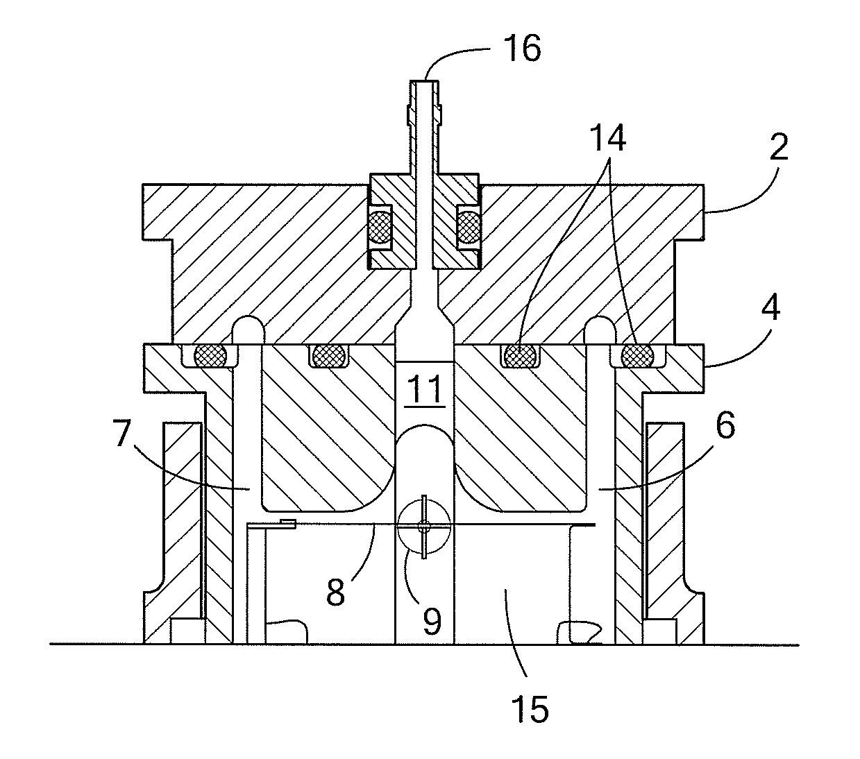
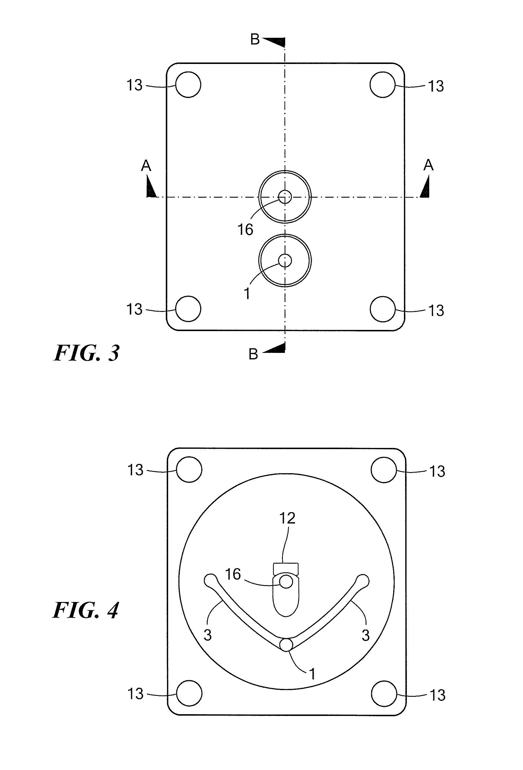
[0042]Various features of an apparatus according to a preferred embodiment of the invention are illustrated in FIGS. 3-7, although equivalent design benefits could also be obtained for differing requirements such as absolute flow rates, containing the same essential elements. The test body in this embodiment is similar to that described in prior art. Various alternative embodiments are mentioned below.

[0043]The gas enters via the inlet gas port (1) in the manifold section (2) and is split internally into two flow channels (3) of equal dimensions. The internal split means that the balance of flow can be controlled via the part dimensions and manufacture rather than by the end user or external plumbing of the device, which may unintentionally cause an extra flow imbalance. However, this split can be implemented external to the device in an alternative embodiment. The gas then passes from the manifold section into the main header (4) which surrounds the paramagnetic suspension assembly...


PUM

PropertyMeasurementUnit
paramagneticaaaaaaaaaa
magnetic fieldaaaaaaaaaa
magnetic susceptibilityaaaaaaaaaa

Abstract

This present invention relates to a device for the measurement of the amount of oxygen in a gas mixture, or other gas with significantly different magnetic susceptibility than the background gas mixture, by the use of a suspended test body in a magnetic field that experiences force due to the magnetic susceptibility of the measurand gas. In order to enable a fast time response for the system with a change in oxygen concentration, a flow regime is presented which allows a fast sweep of the measurement volume combined with adjustable, balanced pressure drops via a flow balancing element (or elements) within the flow channels to independently minimise flow related uncertainties.

Description

CROSS REFERENCE TO RELATED APPLICATIONS[0001]This application claims priority under 35 U.S.C. §119 to United Kingdom patent application No. GB 1102178.9 filed on Feb. 8, 2011, which is incorporated herein by reference.FIELD OF INVENTION[0002]This present invention relates to apparatus for the measurement of the amount of oxygen in a gas mixture, or other gas with significantly different magnetic susceptibility than the background gas mixture, by the use of a suspended test body in a magnetic field that experiences force due to the magnetic susceptibility of the measurand gas.BACKGROUND[0003]The measurement of oxygen gas by its paramagnetic property is a well established technique which is approved for many industrial and medical applications, where it generally provides excellent selectivity, accuracy and reliability. This is because oxygen is one of the few gases which exhibit paramagnetism, meaning it will be strongly attracted by a magnetic field. Most other common gases are diam...

Claims


Application Information

Patent Timeline
Patent Type & Authority Applications(United States)
IPC IPC(8): G06G7/57G01N27/76
CPCG01N27/74
Inventor GASKIN, IAN C.KOVACICH, RICHARD P.EDWARDS, CHRISTOPHER R.HOBBY, JAMES D.LOPEZ, MARTIN
Owner SERVOMEX GRP LTD
Why Eureka
Try Eureka