Power source with overload protection

a power source and overload protection technology, applied in the field of power sources, can solve the problems of high load only in the case of a fault, power loss must be discharged via cooling surfaces or heat sinks, and the maximum power loss of the transistor is often only occurring, so as to prevent overheating of the transistor, reduce power loss, and increase the temperature of the transistor

Inactive Publication Date: 2015-11-17
INIT INNOVATIVE INFORMATIKANWENDUNGEN & TRANSPORT VERKEHRS UND LEITSYSTN
View PDF10 Cites 0 Cited by
  • Summary
  • Abstract
  • Description
  • Claims
  • Application Information

AI Technical Summary

Benefits of technology

[0012]To permit safe operation even in the case of a short circuit, a protective measure is taken that intervenes in the case of a fault and prevents overheating of the transistor. To do this, according to the invention, a temperature-dependent resistor is thermally coupled with the power source transistor. The temperature-dependent resistor is in circuit with the power source as a temperature sensor in such a way that the power output, and thus the power loss, is reduced.
[0013]Simple power sources with the use of a transistor have a resistor on the transistor emitter, which determines the maximum power output of the power source in wide ranges. According to the invention, the temperature-dependent resistor intervenes at exactly this point, namely in that it is connected in such a way that with increasing temperature of the transistor, the temperature-dependent resistor influences the voltage across the resistor on the transistor emitter. If the voltage drops, only a lower current can flow through the resistor and because of this, in turn the output current emitted by the power source is reduced. This means that if the circuit is loaded with a current that is too high, the transistor supplying the output current heats up. Because of the thermal coupling of the transistor with the temperature-dependent resistor, the temperature of the temperature-dependent resistor increases. In turn, this acts on the resistor and leads to a reduction in the output current of the power source. In this way, a type of feedback occurs that provides for prevention of an overload of the transistor and limiting of the current.
[0016]In an exemplary manner, the first transistor is a pnp transistor. The use of pnp transistors has the advantage that power sources can be constructed, in which an output current can be driven toward ground. This makes handling them easier, for example in bus systems. However, an npn transistor can also be used for the power source according to the invention. The mechanisms described apply analogously.
[0018]To improve the temperature stability of the power source, a reference voltage can be generated. With the wiring of the temperature-dependent resistor described above, the reference voltage can be applied across the serial connection of the resistor on the emitter of the first transistor and the emitter-base section of the first transistor. Also, the reference voltage is across the temperature-dependent resistor, which is connected parallel to the named series circuit.
[0020]To improve the independence of the output current from the supply voltage, a current sink can be provided between base and collector of the first transistor. The current sink consists of a second transistor, on the emitter of which a resistor is mounted. In parallel to the base-emitter section of the second transistor and the resistor on the emitter of the second transistor, one or more diodes are connected for generating a reference voltage. The second transistor is designed as an npn transistor.
[0023]A thermal coupling between the temperature-dependent resistor and the first transistor can be facilitated in that the temperature-dependent resistor and the transistor are mounted close to each other. The thermal coupling can be improved in that a heat conducting means is mounted between the first transistor and the temperature-dependent resistor. When the transistor is mounted on a cooling surface, the thermal coupling can be achieved in that the temperature-dependent resistor is thermally coupled with the cooling surface. If the cooling surface is formed of circuit board material, there is a very good thermal conductor, usually copper. Because of this, the temperature-dependent resistor reacts very quickly to heating of the first transistor and load peaks can be intercepted very quickly.

Problems solved by technology

Rather, a maximum power loss in the transistors frequently only occurs in the case of a fault.
Very high loads occur only in the case of a fault, e.g. a defect in a device that is connected or a wiring fault.
This means that, in the case of a short circuit, the power loss must be discharged via cooling surfaces or heat sinks.
During a short circuit, a power loss occurs that results as the product of the maximum supply voltage and the current supplied by the power source.
This means that only the far lower current requirement of normal operation has to be covered and the power loss that then occurs has to be dissipated.

Method used


Image

  • Power source with overload protection
  • Power source with overload protection
  • Power source with overload protection

Examples


Embodiment Construction

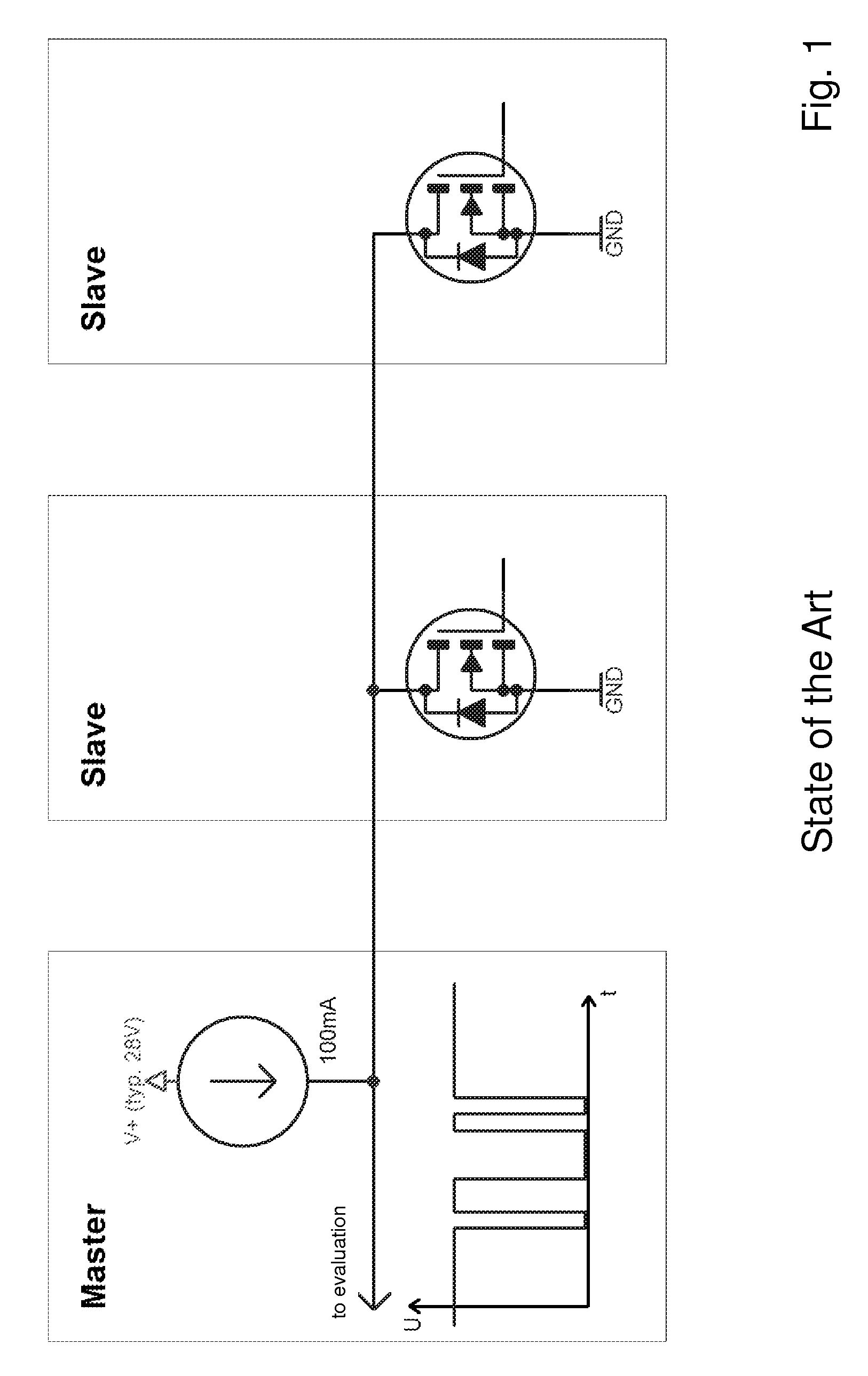
[0029]FIG. 1 shows a schematic structure of a response bus and a typical voltage curve during data transmission in an IBIS vehicle bus. More details can be found in the introductory section of the description.

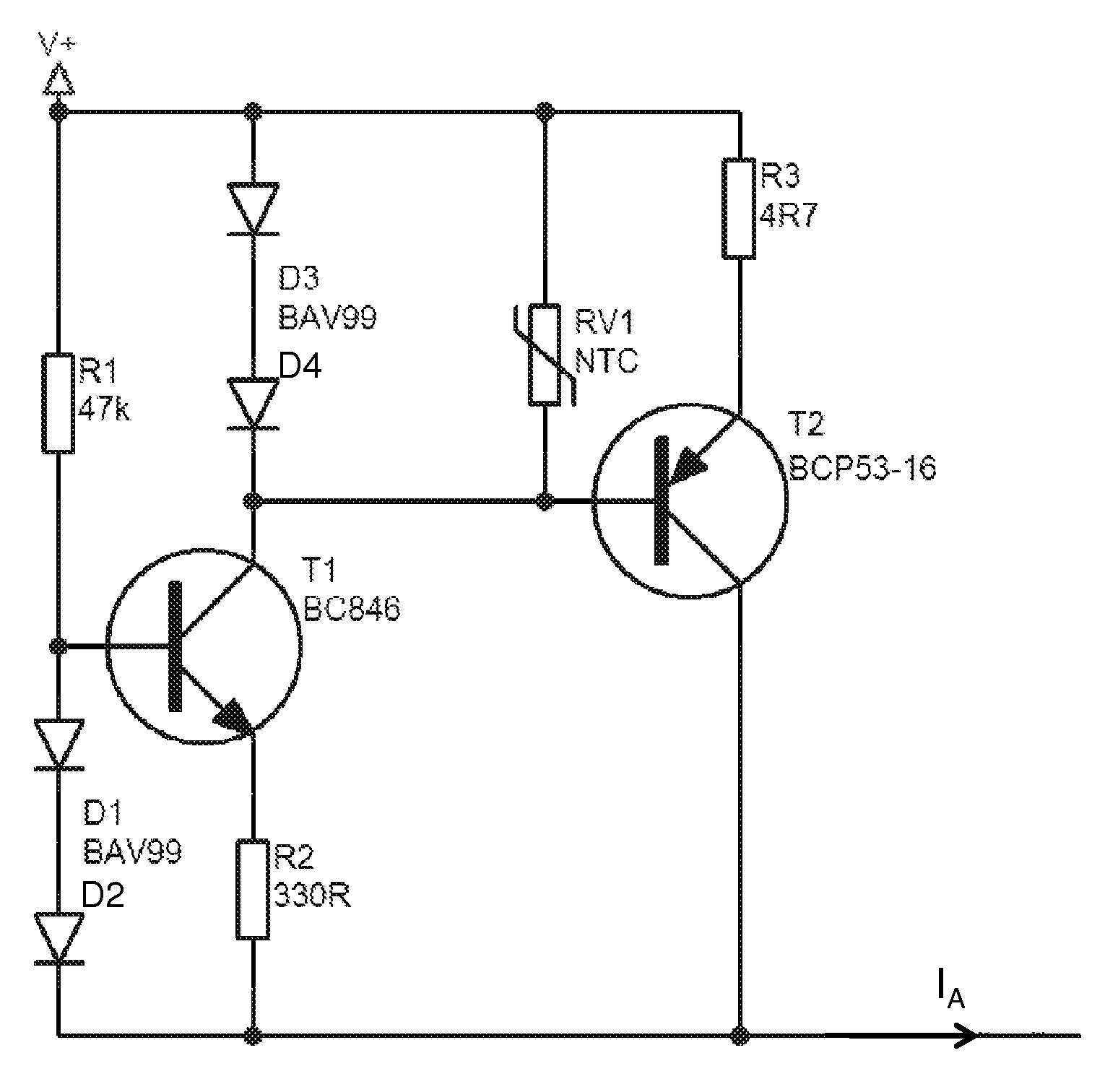
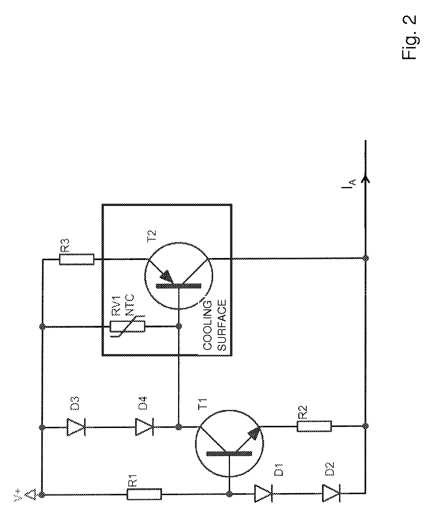
[0030]FIG. 2 shows an exemplary embodiment of a power source according to the invention. The power source is connected to a supply voltage V+ and supplies an output current IA. The output current IA essentially flows through a first resistor R3 that is connected to the voltage supply V+ and the emitter of a first bipolar transistor T2. The first transistor T2 is designed as a pnp transistor. A temperature-dependent resistor RV1 is connected in parallel to the first resistor R3 and the emitter-base section of the first transistor T2. In turn, a series circuit of two diodes D3 and D4 is connected to the temperature-dependent resistor. The base of the first transistor T2 is connected to the collector of a second bipolar transistor T1. The emitter of the second transistor T1 is con...


PUM


Abstract

Power source, in particular for use in a databus in public means of transportation, wherein the power source has a first transistor (T2), and wherein in a normal operating mode of the power source the current (IA) which is conducted through the first transistor (T2) is determined by a first resistor (R3) at the emitter of the first transistor (T2), is characterized with respect to safe operation accompanied by the smallest possible space requirement and lowest possible manufacturing costs in that a temperature-dependent resistor (RV1) is thermally coupled to the first transistor (T2) and that the temperature-dependent transistor (RV1) is connected to the power source in such a way that when the temperature of the first transistor (T2) is rising the temperature-dependent resistor (RV1) influences the voltage across the first resistor (R3) and thereby brings about a reduction in the output current (IA) of the power source.

Description

CROSS REFERENCE TO RELATED APPLICATIONS[0001]This application is a national stage application, filed under 35 U.S.C. §371, of International Application No. PCT / DE2011 / 050044, filed Oct. 11, 2011, which claims priority to and the benefit of German Application No. 10 2010 051 406.3, filed Nov. 16, 2010, the contents of both of which are hereby incorporated by reference in their entirety.BACKGROUND[0002]1. Technical Field[0003]The invention relates to a power source, especially for use with a data bus in public transportation, wherein the power source has a first transistor and wherein, in normal operation of the power source, the current emitted by the first transistor is determined by a first resistor on the emitter of the first transistor.[0004]2. Description of Related Art[0005]In some areas of technology, power sources or current sinks with low precision requirements are needed. One example of this is the supply of a data bus, e.g. the response bus of the IBIS and / or VDS vehicle b...

Claims


Application Information

Patent Timeline
Patent Type & Authority Patents(United States)
IPC IPC(8): G05F3/02G05F3/08
CPCG05F3/02G05F3/08
Inventor GUELTIG, MICHAEL
Owner INIT INNOVATIVE INFORMATIKANWENDUNGEN & TRANSPORT VERKEHRS UND LEITSYSTN
Why Eureka
Try Eureka