Spinal fusion system

a fusion system and spine technology, applied in the field of spine fusion system, can solve the problems of adding a lot of unnecessary morbidity and too much instability to the procedure, and achieve the effect of improving the stability and stability of the procedur

Active Publication Date: 2015-11-24
SPINAL ELEMENTS INC
View PDF14 Cites 18 Cited by
  • Summary
  • Abstract
  • Description
  • Claims
  • Application Information

AI Technical Summary

Benefits of technology

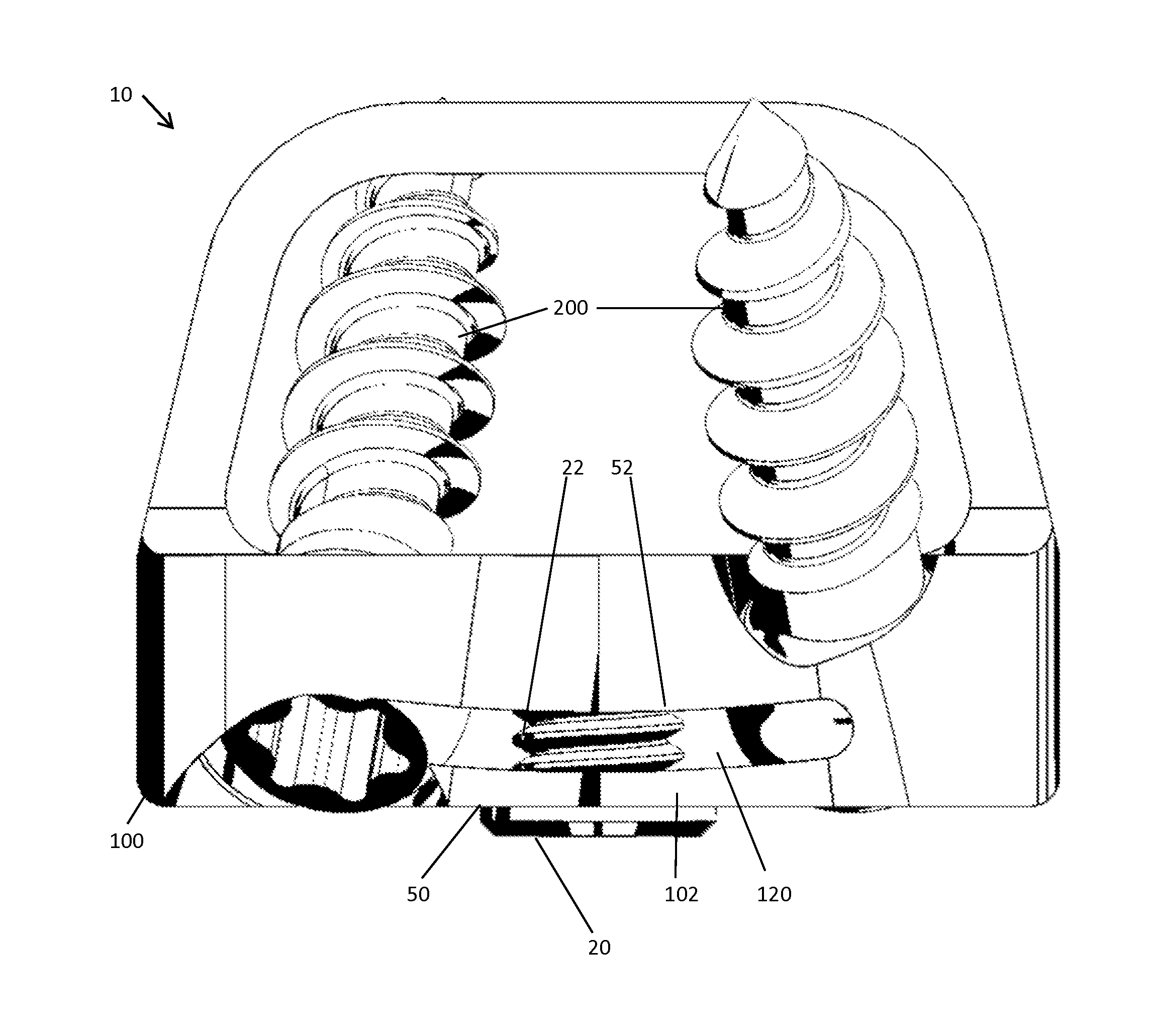
[0010]Another feature of the preferred embodiment is a pair of inserter mounting connectors formed in the bridge. One connector is on each diametrically opposed side of the center opening. Each inserter mounting connector is a void region cut into an edge of the bridge. One is located at a top or first edge and an opposite one at a bottom or second edge to provide a clamping and gripp

Problems solved by technology

This adds a lot of unnecessary morbidity to the procedure and therefore is used much less oft

Method used


Image

  • Spinal fusion system
  • Spinal fusion system
  • Spinal fusion system

Examples


Embodiment Construction

[0021]The present systems and apparatuses and methods are understood more readily by reference to the following detailed description, examples, drawing, and claims, and their previous and following description. However, before the present devices, systems, and / or methods are disclosed and described, it is to be understood that this invention is not limited to the specific devices, systems, and / or methods disclosed unless otherwise specified, as such can, of course, vary. It is also to be understood that the terminology used herein is for the purpose of describing particular aspects only and is not intended to be limiting.

[0022]The following description of the invention is provided as an enabling teaching of the invention in its best, currently known embodiment. To this end, those skilled in the relevant art will recognize and appreciate that many changes can be made to the various aspects of the invention described herein, while still obtaining the beneficial results of the present ...


PUM


Abstract

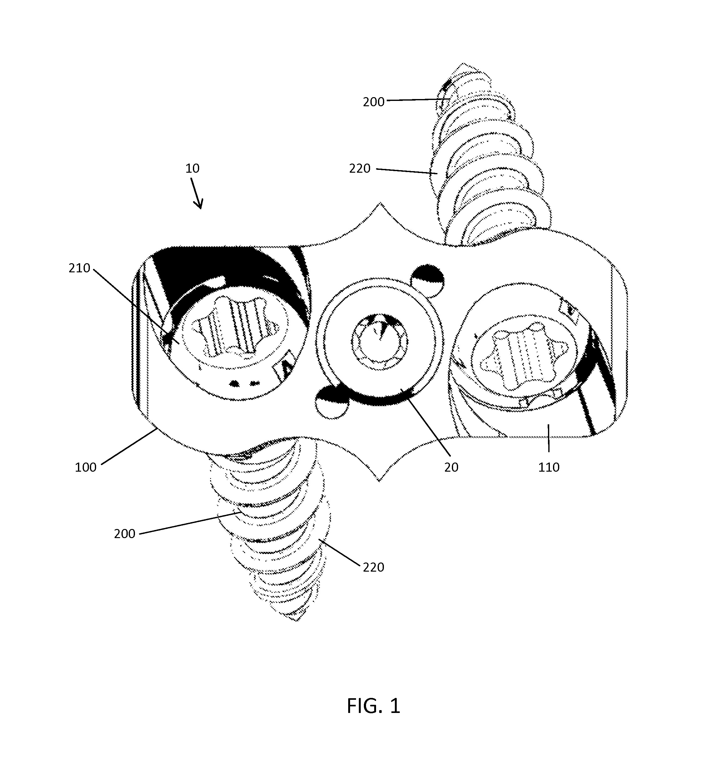
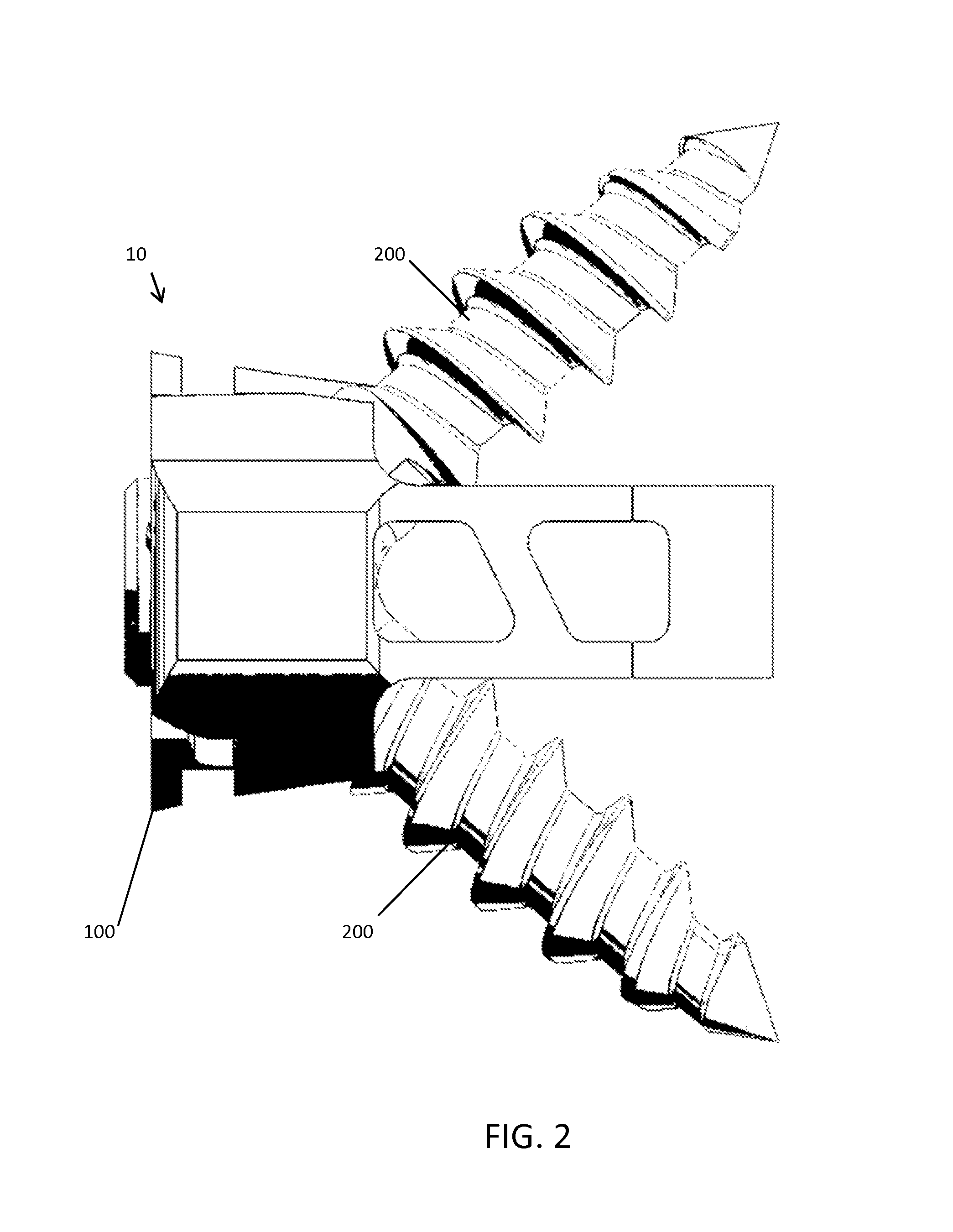
An improved spinal fusion system (10) for positioning between a first and second vertebral body, the system (10) has a body (100), a pair of polyaxial fasteners (220) and a locking bridge (102). The distal end has a slotted opening (120) extending through the body (100) and forming a gap extending between the two or more bore holes (110) to form a deflectable bridge (102) spanning the bore holes (110). The bridge (102) has a center opening (50) for receiving a set screw (20) passing through the bridge (102) into a threaded opening (52) in the body. When the set screw (20) is tightened, it deflects the bridge (102) closing the gap as the bridge (102) contacts an exterior surface of each head (210) of the polyaxial fasteners (200). The angulation of each polyaxial screw (200) is adjustable, controlled by the tightening of the set screw. Initial contact of the bridge (102) with the head (210) of the fastener (200) reduces angulation movement of the shank (220) requiring manual manipulation. Increased tightening of the set screw (20) fixes the angulation as the bridge (102) reduces the gap and increases fastener head contact forces.

Description

TECHNICAL FIELD[0001]Presented herein is a spinal fusion system. More specifically, a spinal fusion system for interbody implantation or corpectomy implantation in spine surgery.BACKGROUND OF THE INVENTION[0002]There are several procedures available to patients with degenerative spine conditions. For example, Anterior Lumbar Interbody Fusion (“ALIF”) has been performed by surgeons since the 1950's. In an ALIF procedure, the disc space is fused by approaching the spine through the abdomen. In the ALIF approach, a three-inch to five-inch incision is made on the left side of the abdomen and the abdominal muscles are retracted to the side. Since the anterior abdominal muscle in the midline (rectus abdominis) runs vertically, it does not need to be cut and easily refracts to the side. The abdominal contents lay inside a large sack (peritoneum) that can also be refracted, thus allowing the spine surgeon access to the front of the spine without actually entering the abdomen. There is also ...

Claims


Application Information

Patent Timeline
IPC IPC(8): A61F2/44A61B17/80
CPCA61F2/4455A61F2/442A61B17/8042A61F2220/0016A61F2/447A61F2002/30505A61F2002/30507A61F2002/30514A61F2002/30593A61F2002/30787A61F2002/30813A61F2002/30904A61F2310/00023
Inventor RADCLIFFE, JEFFREY SCOTTGLATZER, MICHAELJACOB, MARK WILSONTERRELL, REGINALD ANTONIOTALLY, WILLIAM CARLTON
Owner SPINAL ELEMENTS INC
Why Eureka
Try Eureka