Patterned electro-optic displays and processes for the production thereof

a technology of electro-optic displays and patterned electrodes, applied in optics, instruments, optical elements, etc., can solve the problems of inadequate service life of these displays, preventing their widespread use, and gas-based electrophoretic media being susceptible to the same types of problems

Active Publication Date: 2015-11-24
E INK CORPORATION
View PDF87 Cites 75 Cited by
  • Summary
  • Abstract
  • Description
  • Claims
  • Application Information

AI Technical Summary

Problems solved by technology

Nevertheless, problems with the long-term image quality of these displays have prevented their widespread usage.
For example, particles that make up electrophoretic displays tend to settle, resulting in inadequate service-life for these displays.
Such gas-based electrophoretic media appear to be susceptible to the same types of problems due to particle settling as liquid-based electrophoretic media, when the media are used in an orientation which permits such settling, for example in a sign where the medium is disposed in a vertical plane.
Indeed, particle settling appears to be a more serious problem in gas-based electrophoretic media than in liquid-based ones, since the lower viscosity of gaseous suspending fluids as compared with liquid ones allows more rapid settling of the electrophoretic particles.
However, an intrinsic color electro-optic layer poses peculiar difficulties.
Coating such narrow stripes of electro-optic media on a commercial scale, preferably on a roll-to-roll basis, is difficult if not practicably impossible.
Furthermore, commercial coating of at least electrophoretic media is typically effected by slot coating, which is not well adapted for coating such narrows stripes of medium, even when special patterning techniques are employed (see, for example, U.S. Pat. No. 7,910,175).
Additional difficulties are introduced by the relatively high viscosities and heterogeneous nature of many electro-optic media.
Even if one succeeds in coating the necessary narrow stripes of electro-optic media separated by even narrower lands, the difficulties in producing high resolution color displays are not ended.
Maintaining this degree of alignment is extremely difficult, especially if both the display itself and the backplane are flexible and based upon polymeric substrates which may distort slightly under the heat and pressure of lamination.
Alternative arrangements of differing electro-optic media, such as the use of red / green / blue / white media, and use of checkerboard patterns, only exacerbate the difficulties of coating and alignment already discussed.

Method used


Image

  • Patterned electro-optic displays and processes for the production thereof
  • Patterned electro-optic displays and processes for the production thereof
  • Patterned electro-optic displays and processes for the production thereof

Examples


Embodiment Construction

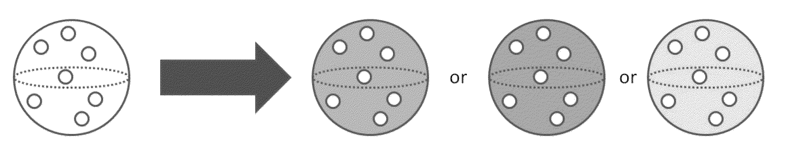
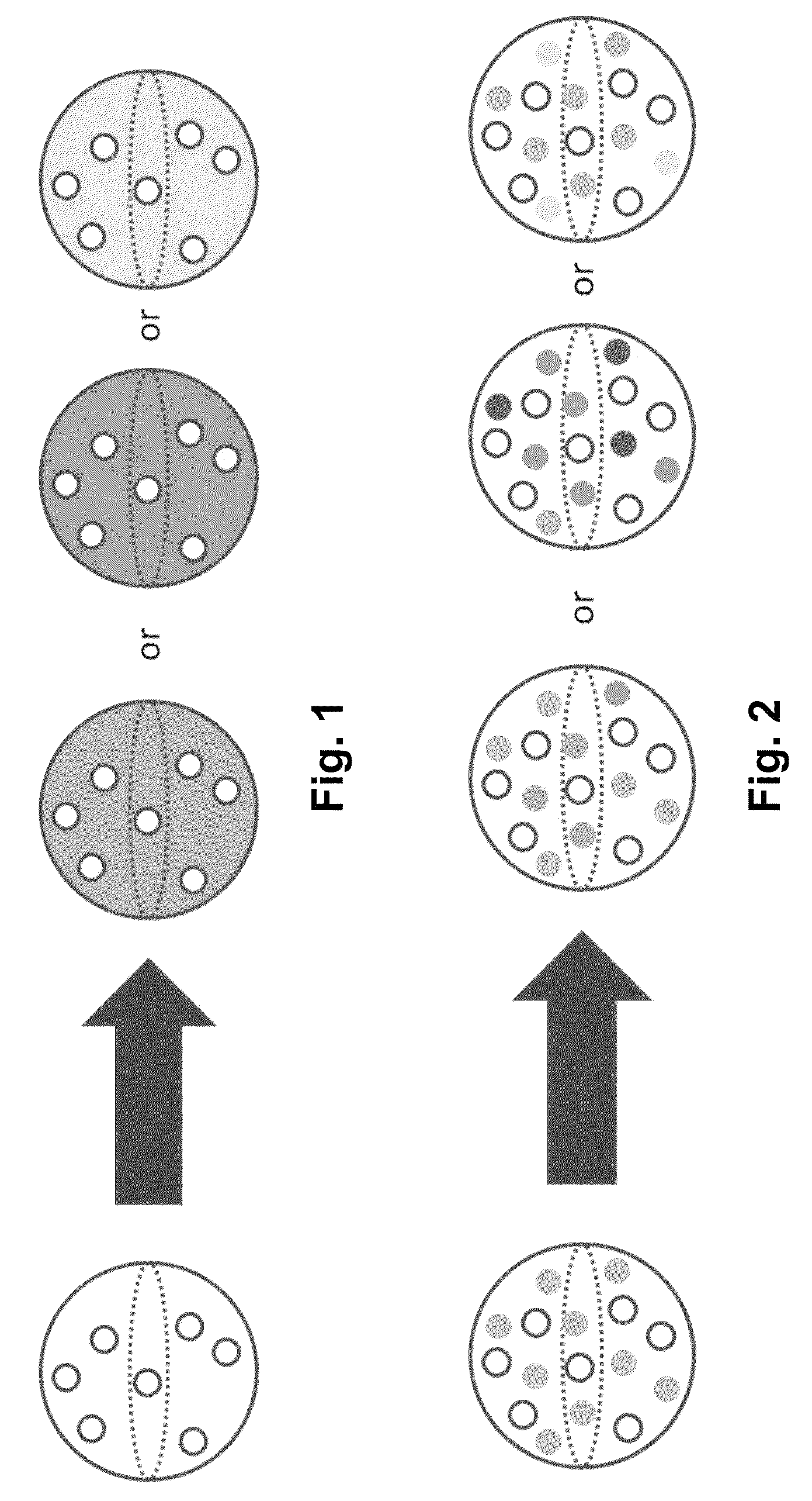
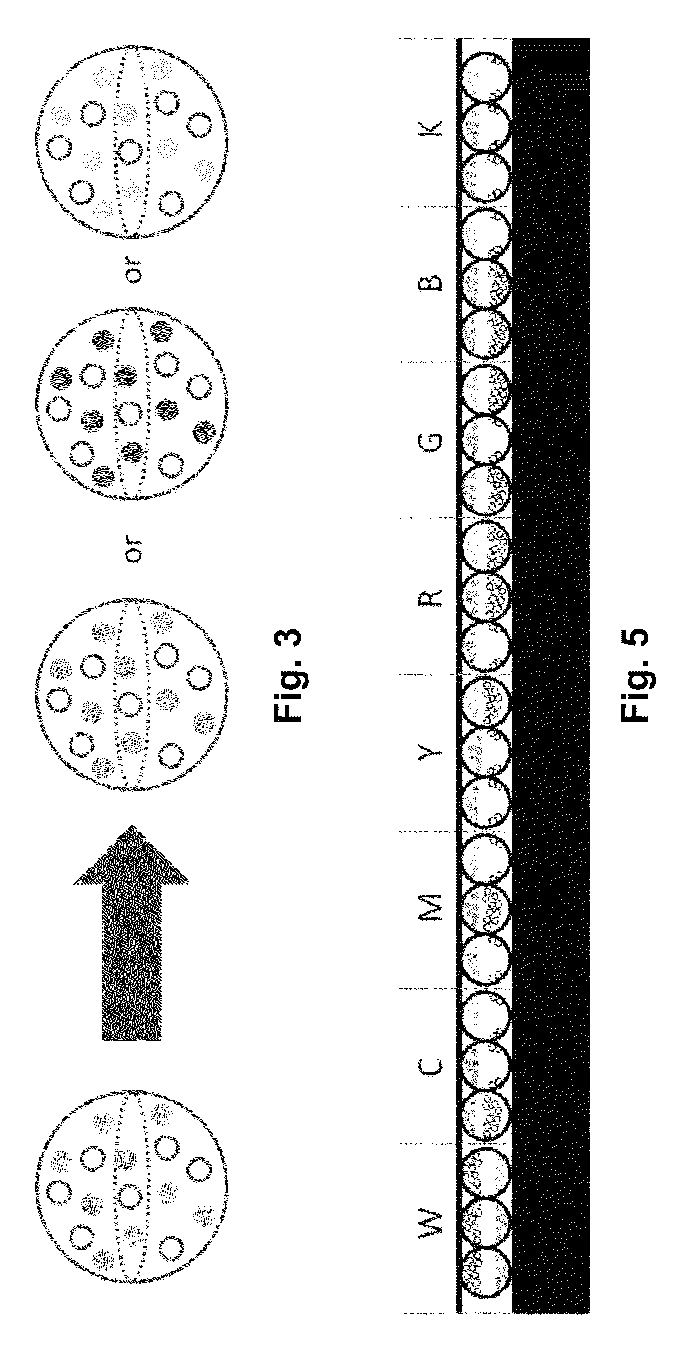
[0048]As will be apparent to those skilled in the imaging art from the Summary of the Invention above, the present invention avoids the problems of coating precisely controlled areas of differing electro-optic media on a substrate by coating a single type of electro-optic medium and thereafter developing two or more colors within the electro-optic medium by exposing the medium to appropriate stimuli. In a preferred form of the invention, the electro-optic medium is present on a backplane before the electro-optic medium is colored; this form of the invention also avoids the lamination problems discussed above, and enables the backplane electrodes to be used as fiducial marks to align the colored areas formed in the electro-optic medium with the electrodes themselves. Thus, essentially the present invention decouple electro-optic medium coating and backplane lamination from color patterning through the use of color-changing dyes within the electro-optic medium.

[0049]It will be apparen...


PUM

PropertyMeasurementUnit
diameteraaaaaaaaaa
thicknessaaaaaaaaaa
thicknessaaaaaaaaaa

Abstract

An electro-optic medium comprises at least one leuco dye such that the electro-optic medium can develop at least two differing colors upon exposure to two or more differing stimuli. The medium allows for development of differing colors in differing areas of the medium, thus allowing formation of intrinsic color within differing areas of a single layer of the same electro-optic medium. In an electrophoretic medium, the colors may be developed within the electrophoretic particles or within the fluid in which the particles are dispersed.

Description

REFERENCE TO RELATED APPLICATIONS[0001]This application claims benefit of Application Ser. No. 61 / 763,209, filed Feb. 11, 2013.[0002]The entire contents of this copending application, and of all U.S. patents and published and copending applications mentioned below, are herein incorporated by reference.BACKGROUND OF INVENTION[0003]This invention relates to patterned electro-optic displays and processes for the production thereof. More specifically, this invention relates to color electro-optic displays in which electro-optic media capable of displaying differing colors (or other desired optical characteristics) are arranged in a regular pattern.[0004]The term “electro-optic”, as applied to a material or a display, is used herein in its conventional meaning in the imaging art to refer to a material having first and second display states differing in at least one optical property, the material being changed from its first to its second display state by application of an electric field ...

Claims


Application Information

Patent Timeline
Patent Type & Authority Patents(United States)
IPC IPC(8): G02F1/167G02B26/02
CPCG02F1/167G02B26/026G02F2001/1678G02F2203/34
Inventor ANSETH, JAY WILLIAMPAOLINI, JR., RICHARD J.
Owner E INK CORPORATION
Why Eureka
Try Eureka