Designing a 3D modeled object

a 3d model and object technology, applied in the field of computer programs and systems, can solve the problems of inability to adjust the base mesh in order, the character line shape and its transition zone is not satisfactory, and the transition zone must be created again on the modified surfa

Active Publication Date: 2015-11-24
DASSAULT SYSTEMES
View PDF55 Cites 7 Cited by
  • Summary
  • Abstract
  • Description
  • Claims
  • Application Information

AI Technical Summary

Problems solved by technology

A problem is that the resulting shape of the character line and its transition zone is not satisfactory when using a subdivision surface.
Tests performed on industrial styling surfaces show that a skilled designer is not able to adjust the base mesh in order to get the expected character line and transition zone.
The drawback is that if the initial subdivision surface is modified afterward, the transition zone must be created again on the modified surface.
The designer is forced to run again steps (2) to (4) by hand, which is time consuming.
This is because steps (2) to (4) are not captured through a history by the CAD system and thus cannot be replayed automatically when the input surface is changed.
Thus, the solutions listed above lack efficiency, notably from a user utilization point of view.

Method used


Image

  • Designing a 3D modeled object
  • Designing a 3D modeled object
  • Designing a 3D modeled object

Examples


Embodiment Construction

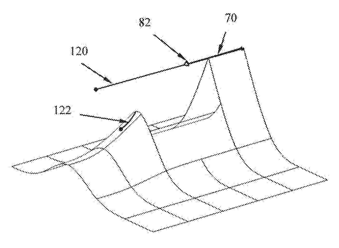
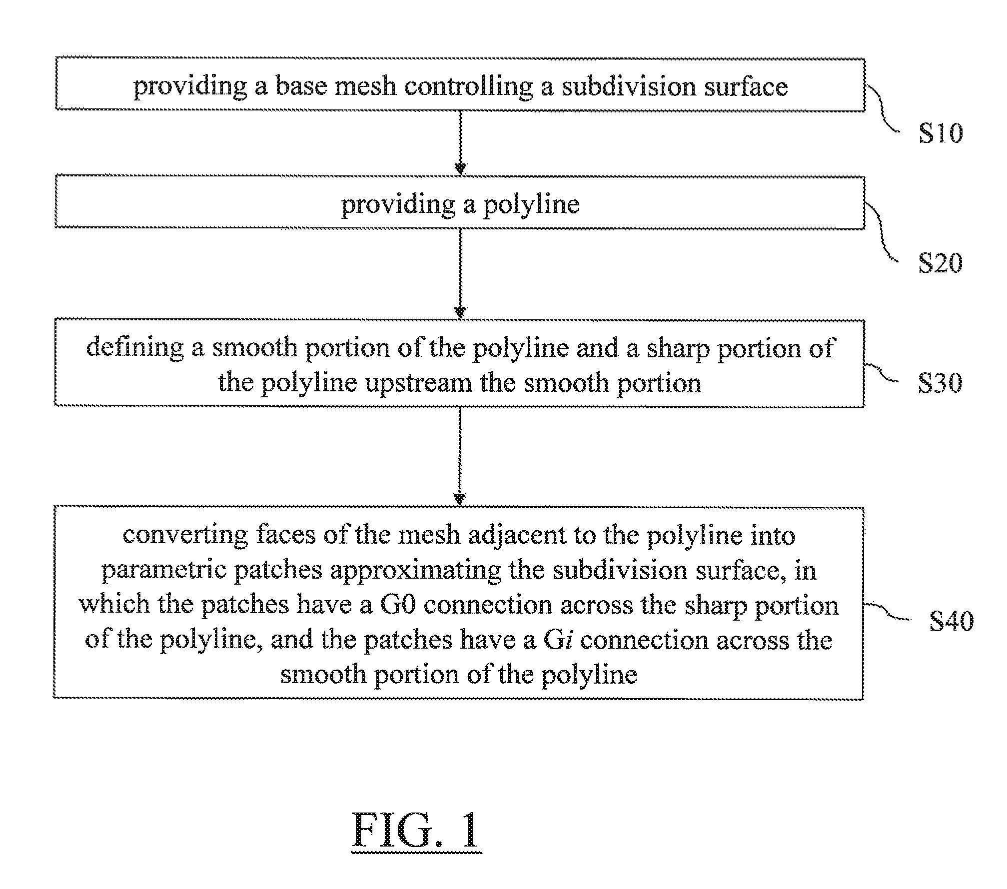
[0040]FIG. 1 shows a flowchart of an example of a computer-implemented method for designing a 3D modeled object. The method comprises the step of providing S10 a base mesh controlling a subdivision surface. The subdivision surface models the 3D modeled object. The method also comprises the step of providing S20 a polyline. A polyline consists of connected edges of the base mesh. The method also comprises the step of defining S30 a smooth portion of the polyline and a sharp portion of the polyline. The smooth portion comprises an extremity of the polyline. The sharp portion is upstream the smooth portion. The method then comprises the step of converting S40 faces of the mesh, which are adjacent to the polyline, into parametric patches. The patches approximate the subdivision surface. The patches have a G0 connection across the sharp portion of the polyline. The patches have a Gi connection across the smooth portion of the polyline, where i is an integer higher or equal to 1 (e.g. i=2...


PUM


Abstract

It is provided a computer-implemented method for designing a 3D modeled object. The method comprises providing a base mesh controlling a subdivision surface. The subdivision surface models the 3D modeled object. The method also comprises providing a polyline consisting of connected edges of the base mesh and defining a smooth portion of the polyline comprising an extremity of the polyline and a sharp portion of the polyline upstream the smooth portion. The method also comprises converting faces of the mesh adjacent to the polyline into parametric patches approximating the subdivision surface. The patches have a G0 connection across the sharp portion of the polyline, and the patches have a Gi connection across the smooth portion of the polyline, where i is an integer higher or equal to 1.Such a method improves the design of a 3D modeled object modeled by a subdivision surface.

Description

RELATED APPLICATION(S)[0001]This application claims priority under 35 U.S.C. §119 or 365 to European, Application No. 12305490.0, filed May 2, 2012. The entire teachings of the above application(s) are incorporated herein by reference.FIELD OF THE INVENTION[0002]The invention relates to the field of computer programs and systems, and more specifically to a method, system and program for designing a 3D modeled object modeled by a subdivision surface.BACKGROUND[0003]A number of systems and programs are offered on the market for the design, the engineering and the manufacturing of objects. CAD is an acronym for Computer-Aided Design, e.g. it relates to software solutions for designing an object. CAE is an acronym for Computer-Aided Engineering, e.g. it relates to software solutions for simulating the physical behavior of a future product. CAM is an acronym for Computer-Aided Manufacturing, e.g. it relates to software solutions for defining manufacturing processes and operations. In suc...

Claims


Application Information

Patent Timeline
Patent Type & Authority Patents(United States)
IPC IPC(8): G06T15/30G06T17/20G06F17/50
CPCG06T17/205G06F17/5086G06F30/17G06T17/20G06F30/00G06F30/12
Inventor MAISONNEUVE, RICHARD
Owner DASSAULT SYSTEMES
Why Eureka
Try Eureka