Apparatus and method for transmitting and receiving control information in a wireless communication system
a wireless communication system and control information technology, applied in wireless communication, multi-frequency code systems, transmission path division, etc., can solve the problems of remarkable degrading communication performance and insufficient information about the resources for harq feedback transmission from an rn, and achieve the effect of increasing communication performan
- Summary
- Abstract
- Description
- Claims
- Application Information
AI Technical Summary
Benefits of technology
Problems solved by technology
Method used
Image

Examples
embodiment 1
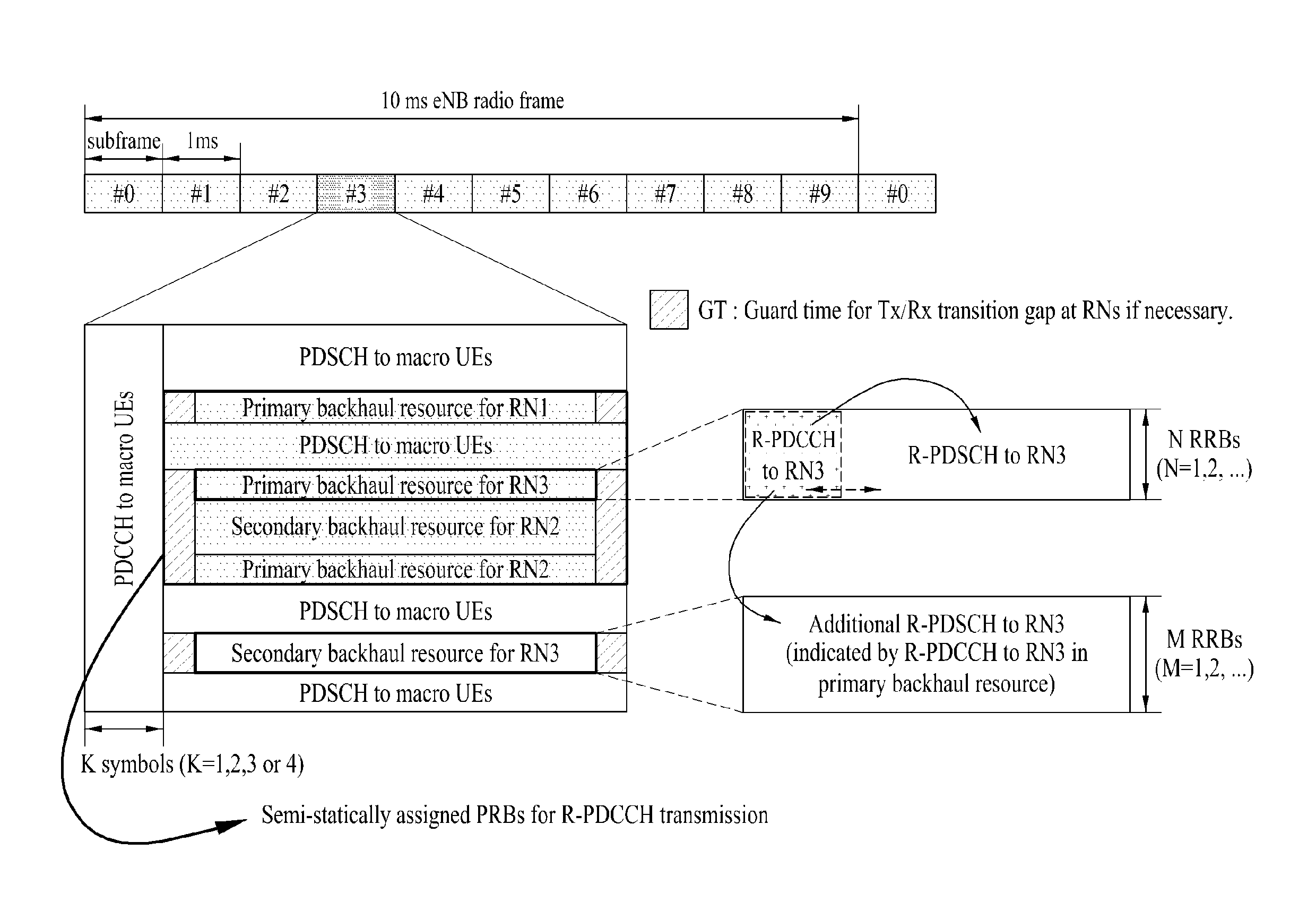
R-CCE Indexing and Associated PUCCH Resource Mapping
[0111]In accordance with an embodiment of the present invention, an offset-based R-CCR indexing method is used. An offset Noffset is defined as a parameter for R-CCE indexing so that R-CCEs are indexed from Noffset to Noffset+NR-CCEmax−1, rather than from 0 to Noffset as described before. Noffset is a semi-static value explicitly signaled to the RN by higher-layer signaling by the eNB or implicitly known to the RN. In this case, Noffset is fixed in every subframe.
[0112]For example, Noffset may be fixed to the maximum number of CCEs that can be transmitted in a PDCCH area determined according to the bandwidth of a cell, a PHICH duration, a CRS transmission structure, and a maximum Control Format Indicator (CFI) value (e.g. if a bandwidth (BW)10 RBs, the CFI is 3). Or Noffset may be a dynamic value that varies in every subframe. Then the eNB directly transmits Noffset or a parameter with which to determine Noffset to the RN on an R-P...
embodiment 2
PUCCH Resource Allocation Offset Setting by Higher-Layer Signaling
[0114]As described before, a PUCCH resource value nPUCCH(1) may be determined by nPUCCH(1)=nCCE+NPUCCH(1) in an FDD system. The eNB may set an offset between an RN and a macro UE regarding a value NPUCCH(1) that the eNB transmits to the macro UE as a cell-specific parameter by higher-layer signaling. That is, the eNB may define a new parameter NPUCCHOffset, signal it to the RN, and define PUCCH resource allocation to the RN by nPUCCH(1)=nCCE+NPUCCHOffset.
[0115]In another method, the eNB may define a new parameter NPUCCH(1)RN rather than it uses the parameter NPUCCH(1) configured for the macro UE and may signal the new parameter NPUCCH(1)RN to the RN by higher-layer signaling. Then PUCCH resource allocation to the RN may be defined by nPUCCH(1)=nCCE+NPUCCH(1)RN.
[0116]The parameters NPUCCHOffset and NPUCCH(1) may be RN-specific. In this case, the eNB may transmit the parameters to each RN by RN-specific higher-layer sig...
embodiment 3
Dedicated PUCCH Resources Allocation for RN
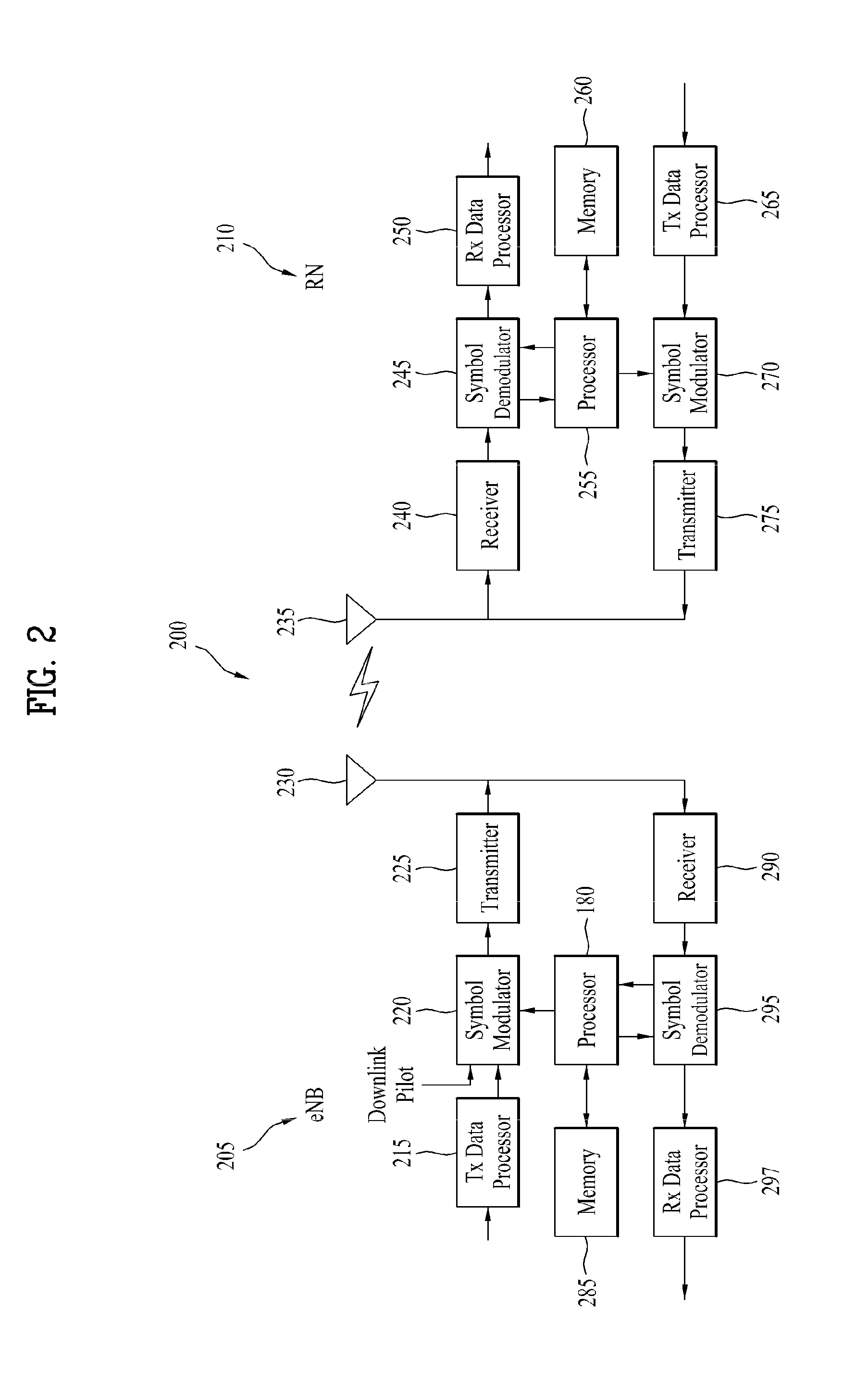
[0117]The eNB may allocate a dedicated PUCCH to an RN. In this case, the eNB may transmit PUCCH resource allocation information nPUCCH(1) (or nPUCCH(1,p) to each RN by higher-layer signaling. A processor 255 of the RN may determine resources for transmission of an HARQ feedback in response to a PDSCH transmission based on the PUCCH resource allocation information received from the eNB. The RN may transmit the HARQ feedback in the determined resources (i.e. resources indicated by the PUCCH resource allocation information) in response to the PDSCH transmission.
PUM
 Abstract
Description
Claims
Application Information
 - R&D
- Intellectual Property
- Life Sciences
- Materials
- Tech Scout
- Unparalleled Data Quality
- Higher Quality Content
- 60% Fewer Hallucinations
Browse by: Latest US Patents, China's latest patents, Technical Efficacy Thesaurus, Application Domain, Technology Topic, Popular Technical Reports.
© 2025 PatSnap. All rights reserved.Legal|Privacy policy|Modern Slavery Act Transparency Statement|Sitemap|About US| Contact US: help@patsnap.com