Method for fabricating a single-piece part for a turbine engine by diffusion bonding

Active Publication Date: 2015-12-01
SN DETUDE & DE CONSTR DE MOTEURS DAVIATION S N E C M A
View PDF5 Cites 2 Cited by
  • Summary
  • Abstract
  • Description
  • Claims
  • Application Information

AI Technical Summary

Benefits of technology

[0027]This layer of fibers serves to reinforce the part. Each fiber comprises a core made of ceramic material (such as silicon carbide, SiC) covered (e.g. by a high-speed coating) in a coating of metal (Ti, Al, B, etc.), this metal preferably being the same as the metal constituting the above-mentioned rings. After diffusion bonding, the part thus comprises a uniform metal matrix that performs a bonding function for the part and a protection function for the fibers that take up the forces to which the part is subjected. This technique makes it possible to increase the

Problems solved by technology

Nevertheless, the methods of the prior art do not make it possible to fabricate parts of non-circular section sin

Method used


Image

  • Method for fabricating a single-piece part for a turbine engine by diffusion bonding
  • Method for fabricating a single-piece part for a turbine engine by diffusion bonding
  • Method for fabricating a single-piece part for a turbine engine by diffusion bonding

Examples


Embodiment Construction

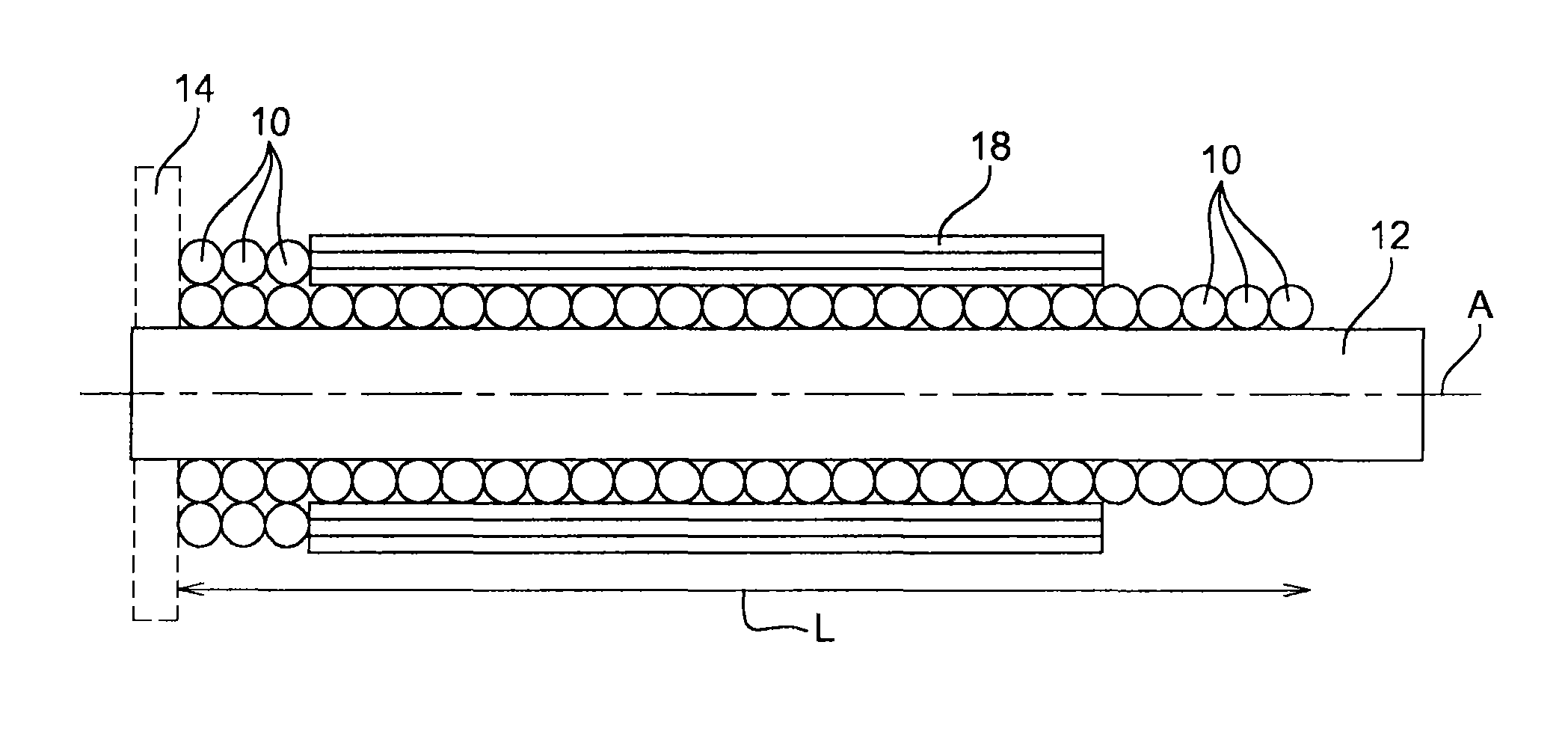
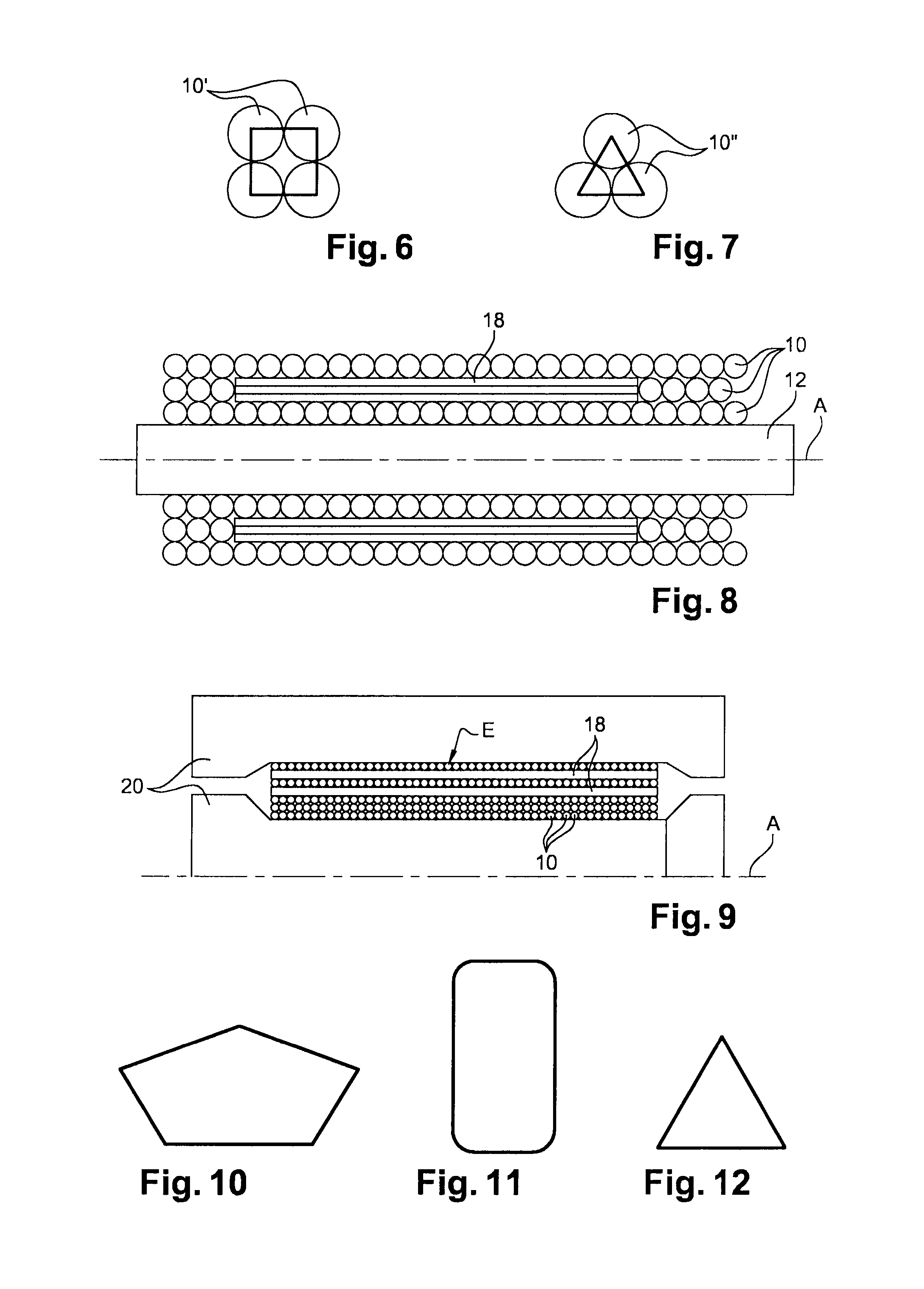
[0039]Steps of a method of the invention are shown diagrammatically in FIGS. 1, 8, and 9, the method serving to fabricate a single-piece part for a turbine engine, such as a shaft, or a disk, or a single-piece bladed ring.

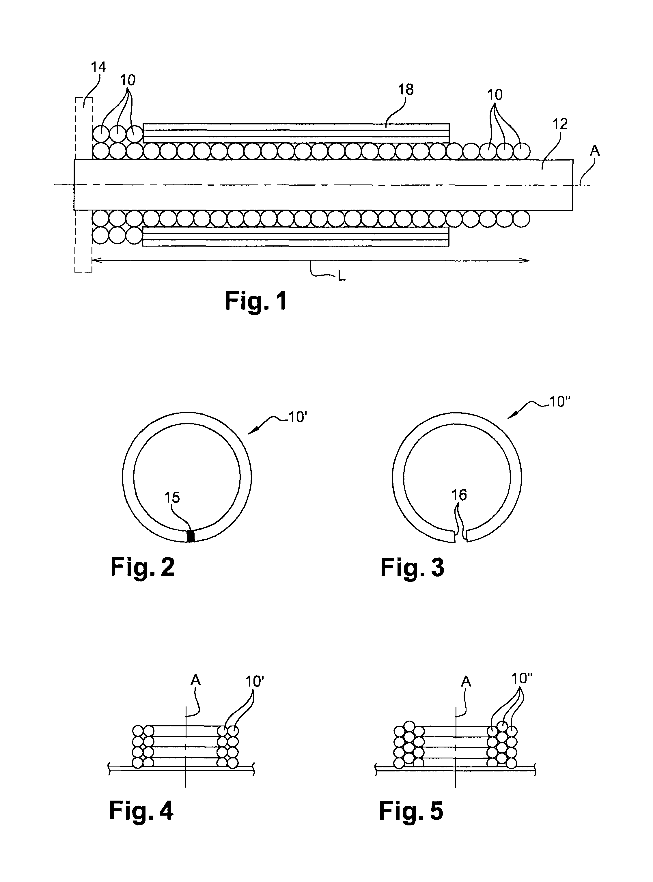
[0040]In a first step shown in FIG. 1, metal rings 10 are engaged on a mandrel 12 and stacked over a predetermined distance L so as to form one or more coaxial and superposed annular layers of metal rings around the mandrel. The rings 10 of a given layer have the same diameter and they are arranged side-by-side along the longitudinal axis A of the mandrel, the thickness of this layer being equal to the diameter of the metal wire from which the rings are made.

[0041]The mandrel 12 in the example shown is cylindrical in shape, but it could have a section of some other shape, e.g. triangular, square, rectangular, or polygonal, as described in greater detail below. The mandrel is arranged vertically or horizontally, and it may be stationary.

[0042]The rings 10 are engage...


PUM

PropertyMeasurementUnit
Shapeaaaaaaaaaa
Circumferenceaaaaaaaaaa

Abstract

A method of fabricating a single-piece part for a turbine engine by diffusion bonding, the method including making a blank for the part around a mandrel, the blank including a plurality of coaxial and superposed annular layers of independent rings of metal wire that are stacked on one another around the mandrel, and subjecting the blank to hot isostatic pressing to obtain a single-piece part, and optionally machining the part.

Description

BACKGROUND OF THE INVENTION[0001]1. Field of the Invention[0002]The present invention relates to a diffusion-bonding method of fabricating a single-piece part for a turbine engine, such as an airplane turboprop or turbojet, the part being constituted, for example, by a power transmission shaft between the main shaft of a turbojet and an accessory gearbox (AGB) for driving accessory equipment of the engine.[0003]2. Description of the Related Art[0004]The AGB shaft is relatively fine and long, with a length of the order of one meter for large diameter engines, and it is generally made in two portions that are arranged end-to-end for reasons of mechanical strength and of withstanding vibration. The adjacent ends of these two portions are guided and centered in rotation by an intermediate bearing that allows the frequencies of resonant modes of vibration to pass.[0005]Proposals have already been made to fabricate such a shaft as a single piece by diffusion bonding. That method consists ...

Claims


Application Information

Patent Timeline
IPC IPC(8): B23K20/02B23P15/04B23P13/00F01D5/02C22C14/00
CPCB23K20/021B23P13/00B23P15/04C22C14/00F01D5/02F05D2230/236Y10T29/49826F05D2240/60F05D2250/141F05D2300/614Y02T50/672Y10T29/49316F05D2230/31Y02T50/60
Inventor GODON, THIERRYDAMBRINE, BRUNO JACQUES GERARD
Owner SN DETUDE & DE CONSTR DE MOTEURS DAVIATION S N E C M A
Why Eureka
Try Eureka