
Marine vessel sliding door system and method

a technology for sliding doors and ships, applied in vessel construction, passenger handling apparatus, vessel ports, etc., can solve problems such as inability to accommodate all circumstances, inducing undesired load on the support column, and introducing design requirements complications, so as to facilitate the access of passengers and facilitate the opening

Active Publication Date: 2015-12-01
SVENDSEN JOEL
View PDF4 Cites 8 Cited by
  • Summary
  • Abstract
  • Description
  • Claims
  • Application Information

AI Technical Summary

Benefits of technology

The present invention is a method and apparatus for a sliding door system for marine vessels. This invention allows for easy access for passengers to get on and off of the vessel from the sliding door system. Overall, this invention improves the accessibility of the vessel for passengers.

Problems solved by technology

Although this width is generally acceptable, it is not accommodating all circumstances.
This limitation can introduce complications in the design requirements.
This configuration induces an undesired load on the support column.
Hinged doors can be dangerous in conditions, such as excessively rough seas, where the door can become unlatch.
Indeed, a swinging door could severely injure one person while he or she is trying to enter or exit through such door when the rolling of the vessel due to rough seas suddenly swings the door toward the person.
Such doors are well known in residential housing and offices, and have also been used in vessels where a swinging door is undesirable, and space is limited.
There are several conventional door systems, however, none of them allow the creation of a sliding access that can then be closed easily to restore the original height and shape of the gunwale of a marine vessel while providing easy entry to the deck of the vessel.

Method used


Image

  • Marine vessel sliding door system and method
  • Marine vessel sliding door system and method
  • Marine vessel sliding door system and method

Examples


Embodiment Construction

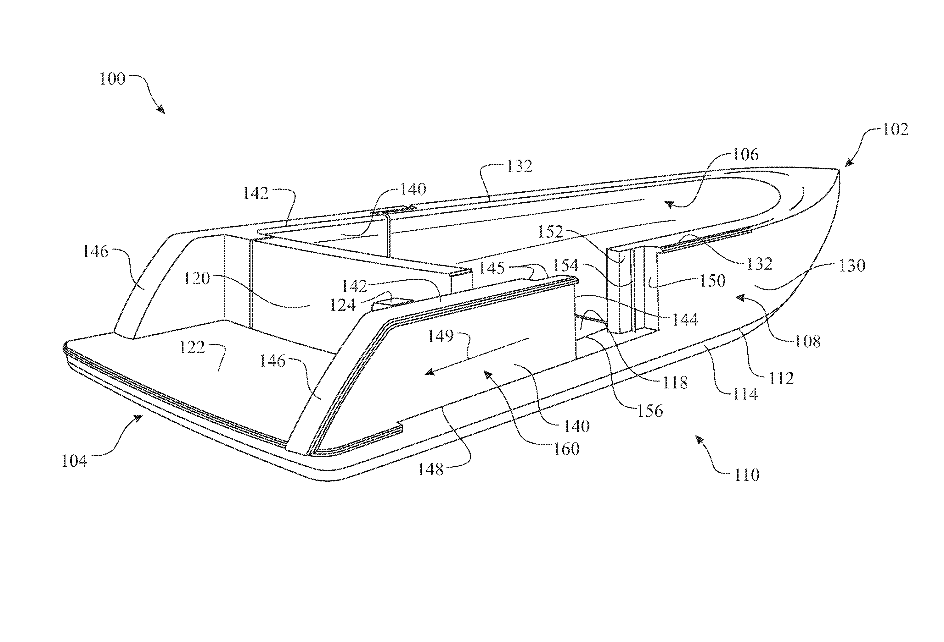
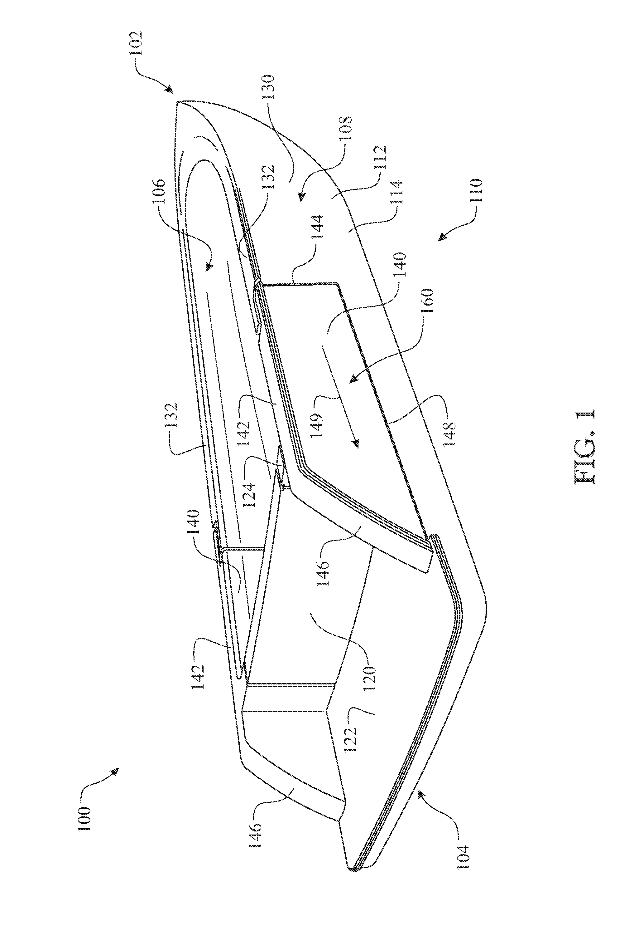
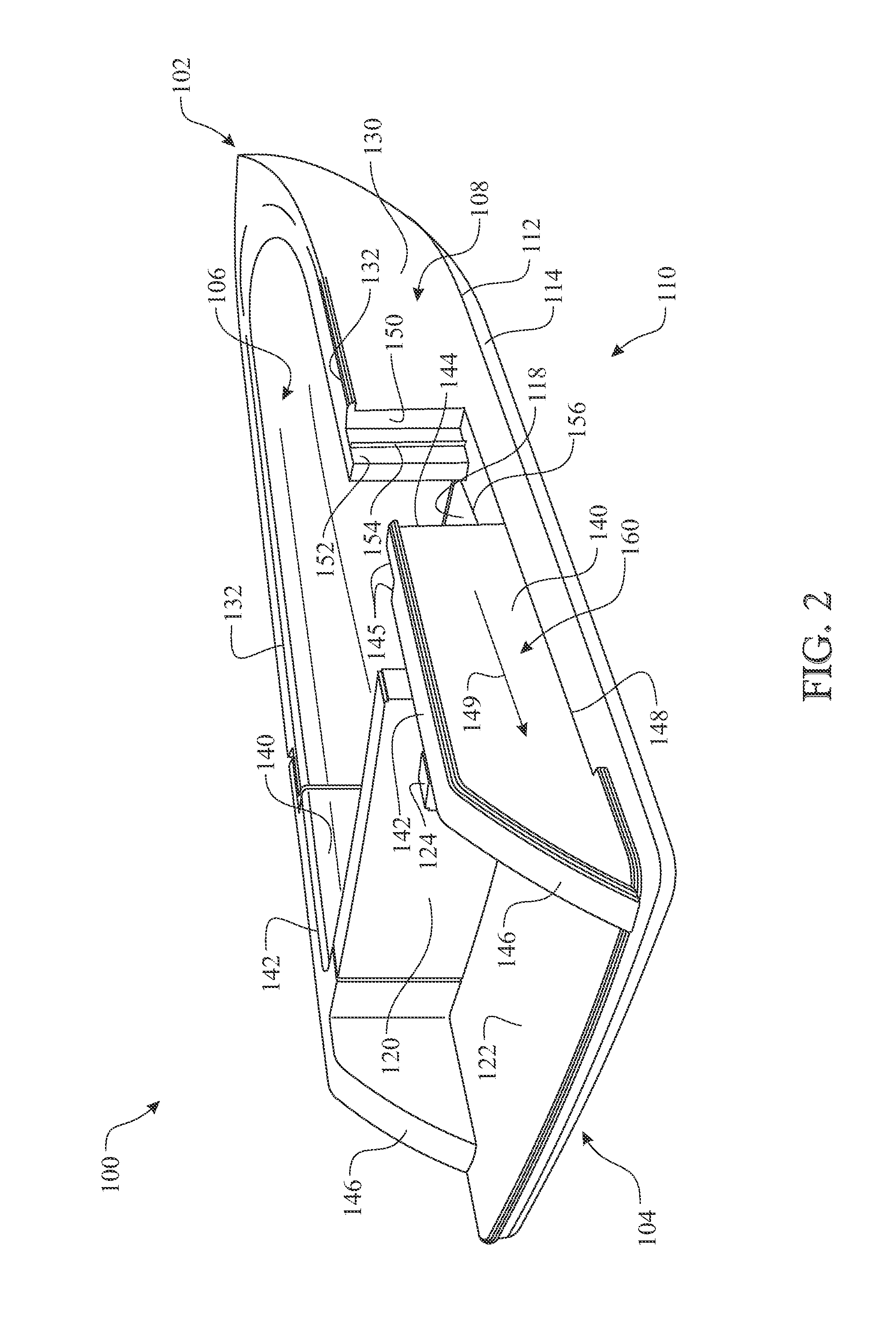
[0049]The following detailed description is merely exemplary in nature and is not intended to limit the described embodiments or the application and uses of the described embodiments. As used herein, the word “exemplary” or “illustrative” means “serving as an example, instance, or illustration.” Any implementation described herein as “exemplary” or “illustrative” is not necessarily to be construed as preferred or advantageous over other implementations. All of the implementations described below are exemplary implementations provided to enable persons skilled in the art to make or use the embodiments of the disclosure and are not intended to limit the scope of the disclosure, which is defined by the claims. For purposes of description herein, the terms “upper”, “lower”, “left”, “rear”, “right”, “front”, “vertical”, “horizontal”, and derivatives thereof shall relate to the invention as oriented in FIG. 1. As used herein, the term “approximates” includes all situations where the appro...


PUM


Abstract

A gunwale sliding section is integrated into a stern portion of a gunwale of a marine vessel. The gunwale sliding section is slideably positioned. The longitudinal motion of the gunwale sliding section is parallel to the gunwale, wherein a sternward motion provides an open configuration and bow-ward motion provides a closed configuration. A rail and slide assembly enables the sliding motion. The stern arrangement of the gunwale sliding section enables a wider span across the opening, thus enhancing embarking and disembarking of the marine vessel. The gunwale sliding section can be manually operated or employ automated mechanisms, such as a hydraulic system, a pneumatic system, a motor driven system, and the like.

Description

CROSS-REFERENCE TO RELATED APPLICATION[0001]This Non-Provisional Utility application claims the benefit of U.S. Provisional Patent Application Ser. No. 61 / 667,526, filed on Jul. 3, 2012, which is incorporated herein in its entirety.FIELD OF THE INVENTION[0002]The present invention relates to a marine vessel sliding gunwale system and method of use, and more particularly, a marine vessel sliding gunwale system useful for a vessel having a sliding door gunwale that can be easily opened, and provide a broad passageway enabling easy egress for passengers and cargo.BACKGROUND OF THE INVENTION[0003]Dimensions of an opening through a gunwale governs the accessibility of an individual and passage of cargo between a dock and a deck of a marine vessel. The passageway is limited by a height of the opening and a width of the opening. The height is limited by the distance between decks. The width is limited by the horizontal distance across the opening. The opening is commonly governed by the re...

Claims


Application Information

Patent Timeline
Patent Type & Authority Patents(United States)
IPC IPC(8): B63B19/18B63B43/26B63B19/00B63B27/14
CPCB63B43/26B63B27/14B63B19/00B63B19/08B63B27/146B63B29/00B63B2017/045B63B2029/022
Inventor SVENDSEN, JOEL
Owner SVENDSEN JOEL
Learn More