Bi-tapered spool for wire braiding machines

a wire braiding machine and bobbin technology, applied in the direction of braiding, thin material processing, textiles and papermaking, etc., can solve the problems of affecting the continuity of braiding and impede production, and achieve the effect of preventing the formation, propagation and buildup of wire winding defects

Active Publication Date: 2015-12-01
FORT WAYNE METALS RES PROD CORP
View PDF37 Cites 14 Cited by
  • Summary
  • Abstract
  • Description
  • Claims
  • Application Information

AI Technical Summary

Benefits of technology

[0009]The present disclosure provides a spool for use in a wire braiding machine, for example, the spool having a “bi-tapered” design including a central cylindrical section and a pair of tapered (e.g., frusto-conical or parabolic) flanges having surfaces that slope inwardly toward the cylindrical section. In this manner, the spool provides a progressively widening wire fill area, as measured along a direction parallel to the rotational axis of the bobbin, as the wound wire advances progressively radially outwardly from the cylindrical section. This widening wire fill area aids in preventing the formation, propagation and buildup of wire winding defects, such that the wire is more likely to unspool or pay-out from the spool without losing tension, snagging or breaking.

Problems solved by technology

Winding defects such as build-up 28 can cause snagging and / or breakage of the wire 16 upon pay-out during operation of the braiding machine 10, which in turn disrupts the continuity of braided construct 20 and necessitates shutdown of machine 10 and replacement of spool 14.
These consequences, in turn, may impedes production of construct 20, generates waste and may result in suboptimal mitigation strategies by the machine operator, such as using spools 14 that are less than completely filled with wound constituent wire 16.

Method used


Image

  • Bi-tapered spool for wire braiding machines
  • Bi-tapered spool for wire braiding machines
  • Bi-tapered spool for wire braiding machines

Examples


##ic example 1

Prophetic Example 1

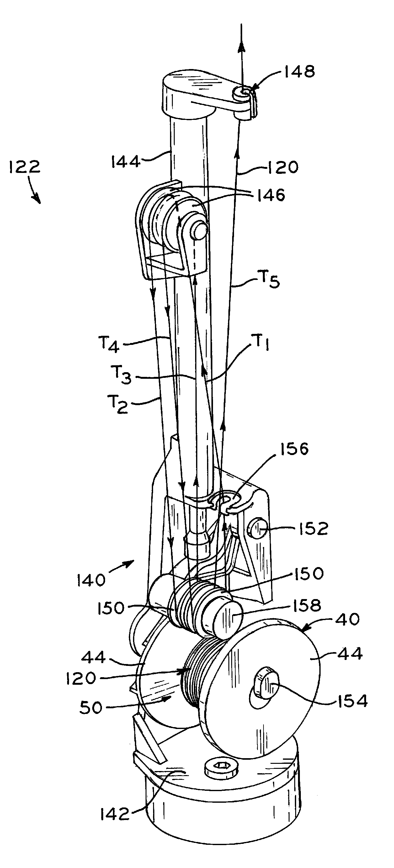
[0075]The spools of FIGS. 4A-11 can used to receive wire 120 having a diameter of less than 1 mm, and in some cases less than or equal to 0.10 mm. A first end of the wire is engaged within the wire winding slot, and the wire is then continuously wound onto spool 40 in a layered, side-by-side alternating fashion as viewed from a side of spool 40, with successive layers of wire 120 overlapping one another as wire 120 is wound onto spool 40. The “bi-tapered” design of spool 40 permits the width of the layers, as viewed from the side of spool 40, to continuously increase as the wire layers are built up radially outwardly onto spool 40 along a wire winding direction transverse to the longitudinal axis L1-L1 of barrel 42 of spool 40. After a desired amount of wire 120 is wound onto spool 40, wire 120 is cut to provide a second end which is then secured to the spool, such as via a piece of tape.

[0076]When several such spools are used in a wire braiding machine, the occur...

working example 1

1. EXPERIMENTAL TECHNIQUE

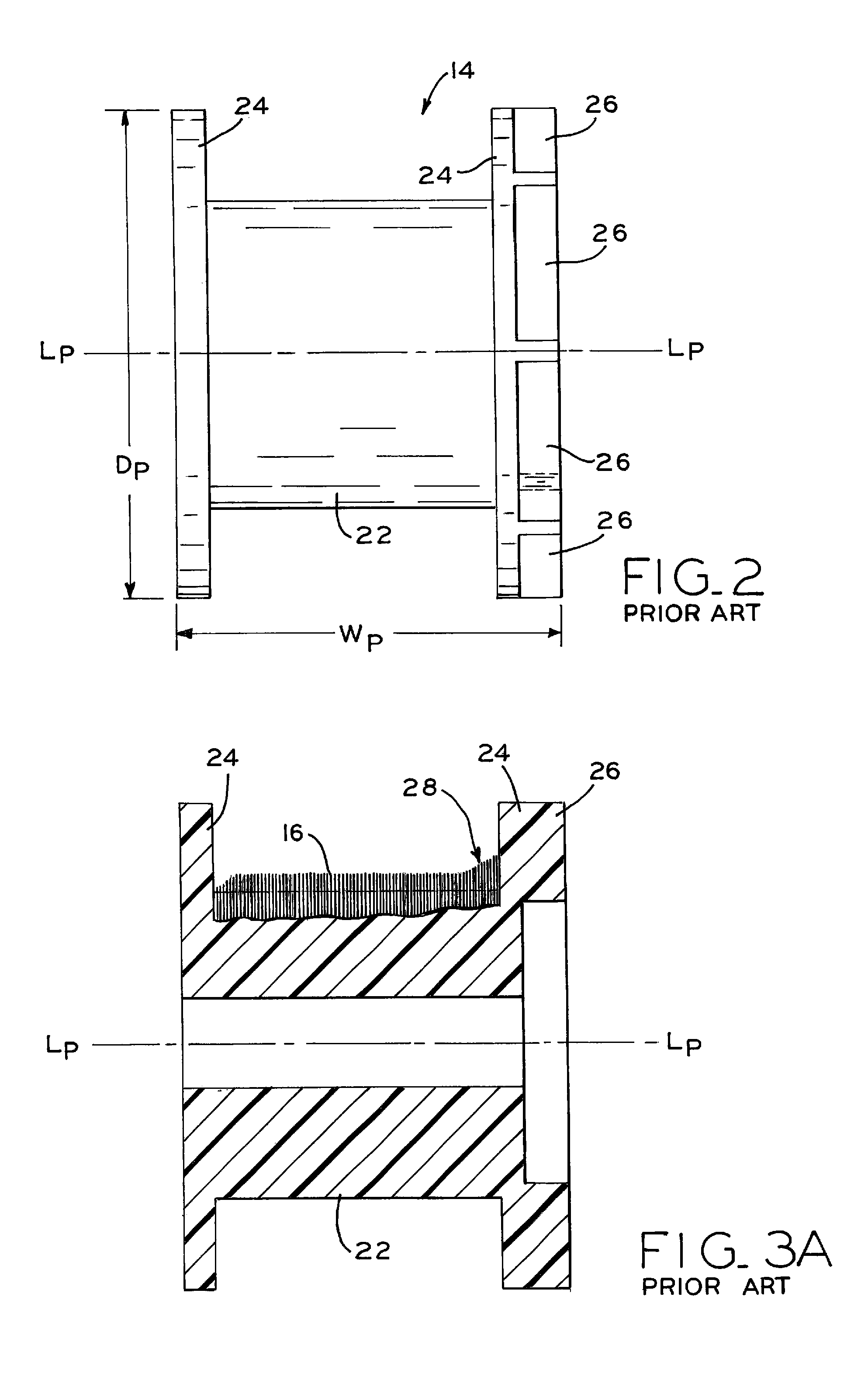
[0077]In this working example, several bobbins made in accordance with the present disclosure, and having different geometrical parameters, were tested in a braiding machine made by Kórting Nachfolger Wilhelm Steeger GmbH & Co KG, illustrated as braiding machine 100 in FIGS. 12-18. As a control, known bobbins lacking a tapered profile (e.g., bobbin 14 shown in FIG. 2) were also tested under the same conditions as the present bobbins.

[0078]Standard statistical methods, including Taguchi methods for Design of Experiments, were used to evaluate the effect of seven factors on the performance of the wire braiding machine. The performance of the trials was evaluated based upon the number of wire breaks occurring during a run of the machine. A break was defined as a fracture in a single braiding wire anywhere within the payoff carrier (which causes the braiding machine to stop operation).

[0079]Percent contribution of the various factors, as such factors relate to t...


PUM


Abstract

A spool for use in a wire braiding machine, for example, which has a “bi-tapered” design including a central cylindrical section and a pair of tapered (e.g., frusto-conical or parabolic) flanges having surfaces that slope inwardly toward the cylindrical section. In this manner, the spool provides a progressively widening wire fill area, as measured along a direction parallel to the rotational axis of the bobbin, as the wound wire advances progressively radially outwardly from the cylindrical section. This widening wire fill area aids in preventing the formation, propagation and buildup of wire winding defects, such that the wire is more likely to unspool or pay-out from the spool without losing tension, snagging or breaking.

Description

CROSS REFERENCE TO RELATED APPLICATIONS[0001]The present application claims the benefit under Title 35, U.S.C. Section 119(e) of U.S. Provisional Patent Application Ser. No. 61 / 636,176, filed Apr. 20, 2012 and entitled BI-CONICAL SPOOL FOR WIRE BRAIDING MACHINES, the entire disclosure of which is hereby expressly incorporated herein by reference.BACKGROUND[0002]1. Technical Field[0003]The present disclosure relates to spools or bobbins for use with wire braiding machines, for example and, in particular, relates to an improved spool having a design which is useful for preventing snagging of wire upon pay-off of the wire from the spool during operation of a wire braiding machine.[0004]2. Description of the Related Art[0005]A schematic view of wire braiding machine 10 is shown in FIG. 1, including rotatable carousel 12 holding a plurality of spools 14 each containing a fine diameter wire 16 wound around spools 14. During operation of braiding machine 10, constituent wires 16 pay-off fr...

Claims


Application Information

Patent Timeline
Patent Type & Authority Patents(United States)
IPC IPC(8): D04C3/16B65H54/02B65H75/02
CPCB65H54/02D04C3/16B65H75/02B65H49/32B65H75/148B65H2701/31B65H55/00B65H75/30B65H2701/36
Inventor GALLMEYER, JEFFERY L.MICHAEL, MARK S.FERENS, JASON W.
Owner FORT WAYNE METALS RES PROD CORP
Why Eureka
Try Eureka