Condition based lifing of gas turbine engine components

a gas turbine engine and component technology, applied in the field of gas turbine engines, can solve problems such as fatigue damage and creep of the various components of the gas turbine engin

Active Publication Date: 2015-12-01
SOLAR TURBINES
View PDF27 Cites 5 Cited by
  • Summary
  • Abstract
  • Description
  • Claims
  • Application Information

AI Technical Summary

Problems solved by technology

The operating conditions of the gas turbine engine result in creep and fatigue damage to the various components of the gas turbine engine.

Method used


Image

  • Condition based lifing of gas turbine engine components
  • Condition based lifing of gas turbine engine components
  • Condition based lifing of gas turbine engine components

Examples


Embodiment Construction

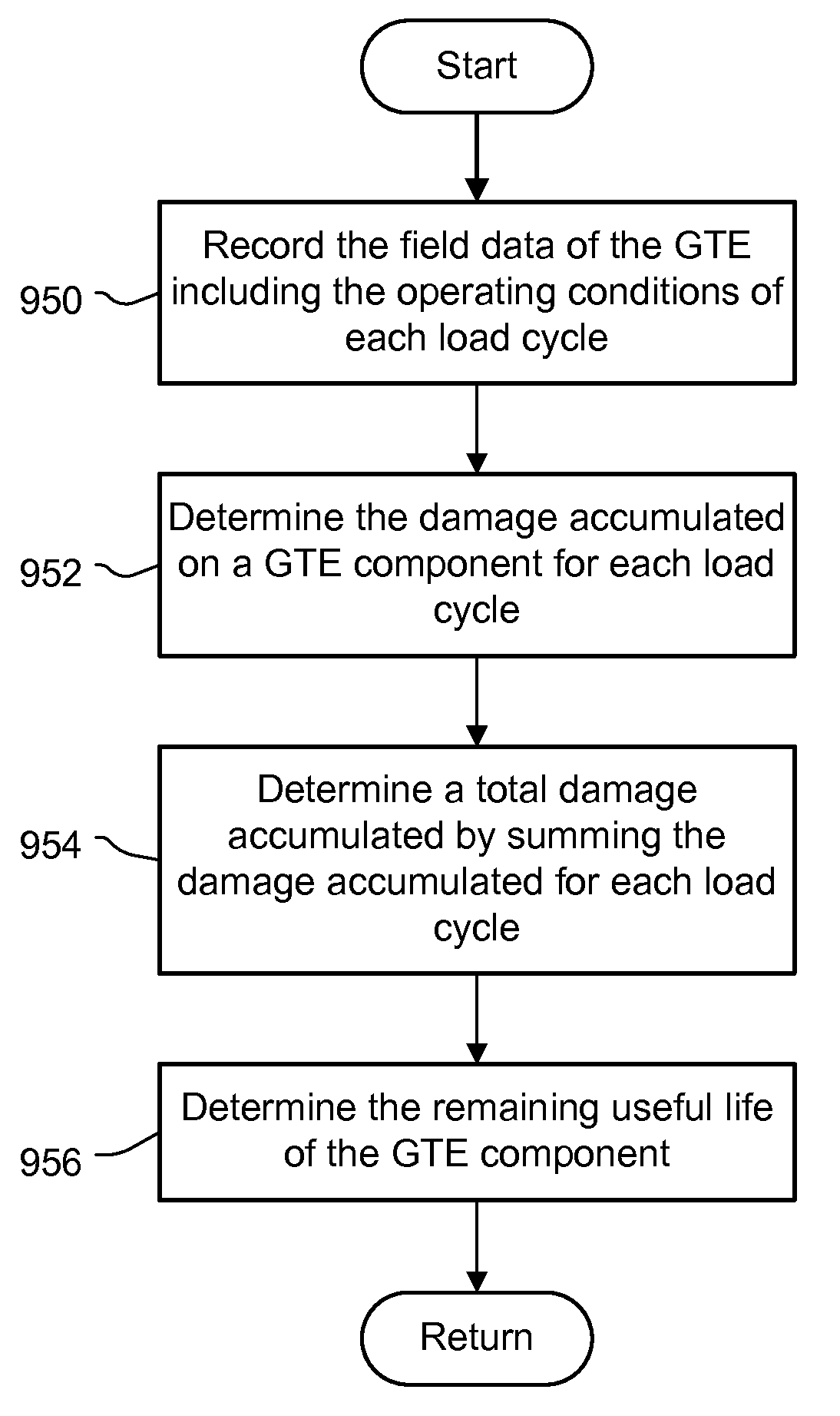
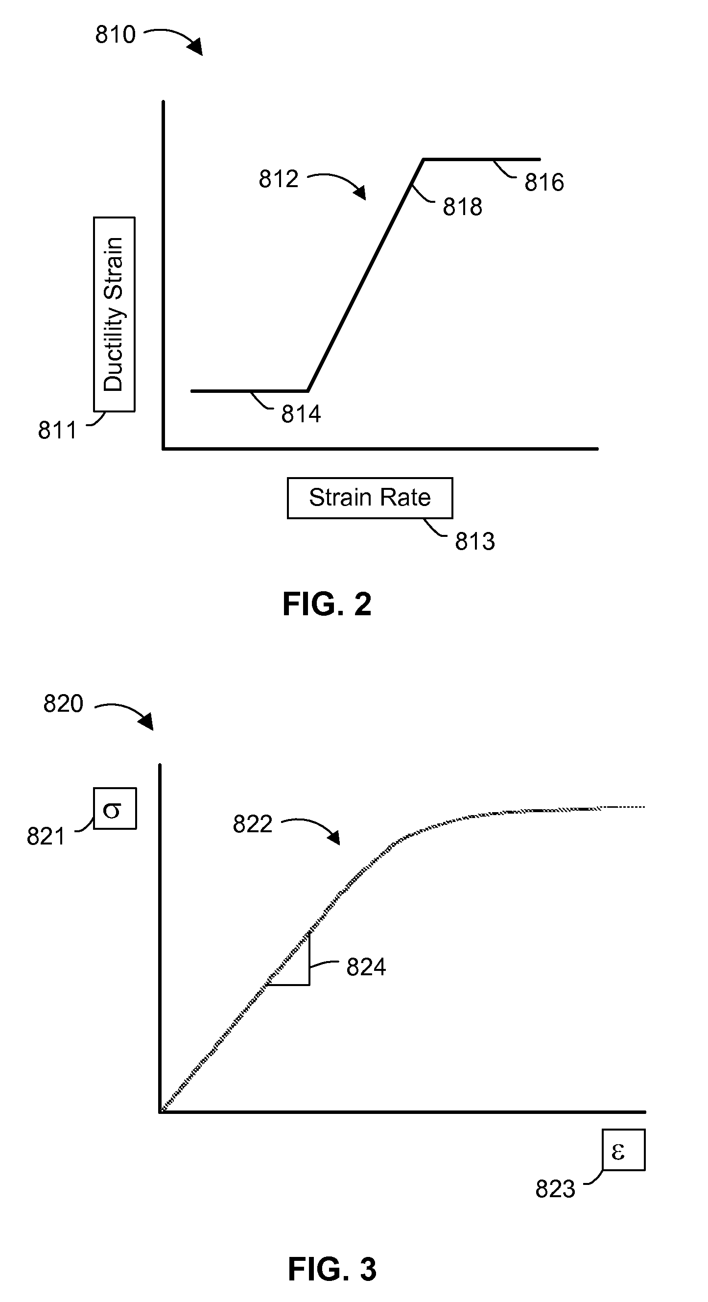
[0014]The systems and methods disclosed herein include a gas turbine engine and a system for determining the remaining useful life of life limited components for a gas turbine engine. The systems and methods use a ductility exhaustion approach to combine the damaging effects of creep and fatigue. Ductility exhaustion is based on strain rate of both the plastic response during a transient portion of the load cycle, defined as the cyclic or fatigue component and the strain rate from the viscoplastic response during the dwell portion of the load cycle or creep component. The strain rate for each inelastic component is used to determine the available ductility from the material's ductility exhaustion curve. The available ductility at each strain rate is then compared with the amount of strain accumulated during that particular inelastic portion of the load cycle. Damage is considered to be the ratio of accumulated strain at a given strain rate relative to the available strain. Damage ca...


PUM


Abstract

A system and methods for the condition based lifing of a gas turbine engine component is disclosed. The system and methods determine the stress and caused by fatigue and creep for each load cycle of the gas turbine engine, and use a ductility exhaustion method to combine the fatigue and creep strain rates determined from the fatigue and creep stresses to determine the remaining useful of the gas turbine engine component.

Description

TECHNICAL FIELD[0001]The present disclosure generally pertains to gas turbine engines, and is more particularly directed toward a condition based lifing process and system for components of a gas turbine engine.BACKGROUND[0002]Gas turbine engines include an inlet, a compressor section, a combustor section, a turbine section, and an exhaust. The operating conditions of the gas turbine engine result in creep and fatigue damage to the various components of the gas turbine engine. Processes and systems for determining the life of turbine components are used to predict when the components might fail so that the components can be replaced prior to failure.[0003]U.S. Patent App. No. 2010 / 0153080 to K. Khirullah is directed to a method for lifespan modeling for a turbine engine component that includes determining a design-phase model of the lifespan of an turbine engine component; fusing the design-phase model with sensor data collected during operation of the turbine engine component to pr...

Claims


Application Information

Patent Timeline
Patent Type & Authority Patents(United States)
IPC IPC(8): G01M15/14G07C5/00
CPCG07C5/006G01M15/14G05B23/0283
Inventor GREEN, RICHARD JAMESNOVARESI, MARK ALFREDBOLLAPRAGADA, SUDHAKAR
Owner SOLAR TURBINES
Why Eureka
Try Eureka