Method and system for controlling an industrial process

a technology for industrial processes and industrial processes, applied in the direction of program control, total factory control, instruments, etc., can solve the problems of operator strain injuries, user interfaces that are non-intuitive, etc., and achieve the effect of simplifying the monitoring and control of an industrial process

Active Publication Date: 2015-12-01
ABB (SCHWEIZ) AG
View PDF3 Cites 6 Cited by
  • Summary
  • Abstract
  • Description
  • Claims
  • Application Information

AI Technical Summary

Benefits of technology

[0006]In view of the above, a general object of the present disclosure is to simplify the monitoring and control of an industrial process for the process operator.
[0013]By displaying the set of process related images in succession, in a slide-show type of manner, an operator may be able to monitor the industrial process parts shown by the set of process related images without having to interact with an input unit of the display device in order to browse trough the different process related images when monitoring the industrial process. The work of the operator is thereby simplified, and the risk of strain injuries to the operator is reduced. Moreover, the operator's attention is immediately drawn to a process related image associated with an abnormal situation as soon as an abnormal situation occurs due to the fact that the relevant process related image, i.e. the process related image which is associated with the process variable having the status value outside the predetermined accepted range is shown in response to receiving process variable data indicating that a process variable has a status value outside a predetermined accepted range. Since an operator may be responsible of monitoring a plurality of parts of the industrial process, the direct displaying of an affected part of the process allows the operator to act within a very short time after the abnormal situation has occurred.

Problems solved by technology

Existing industrial system control systems have several drawbacks, including having user interfaces which are non-intuitive and which provide strain injuries to the operators.

Method used


Image

  • Method and system for controlling an industrial process
  • Method and system for controlling an industrial process
  • Method and system for controlling an industrial process

Examples


Embodiment Construction

[0033]The inventive concept will now be described more fully hereinafter with reference to the accompanying drawings, in which exemplifying embodiments are shown. The inventive concept may, however, be embodied in many different forms and should not be construed as limited to the embodiments set forth herein; rather, these embodiments are provided by way of example so that this disclosure will be thorough and complete, and will fully convey the scope of the inventive concept to those skilled in the art. Like numbers refer to like elements throughout the description.

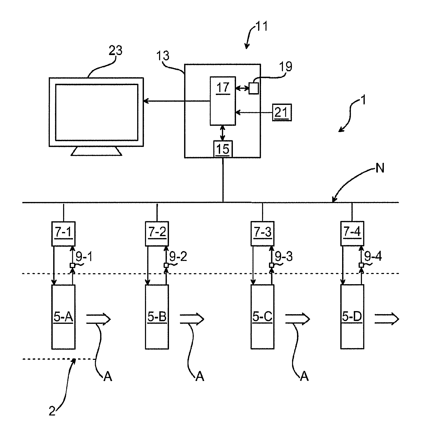
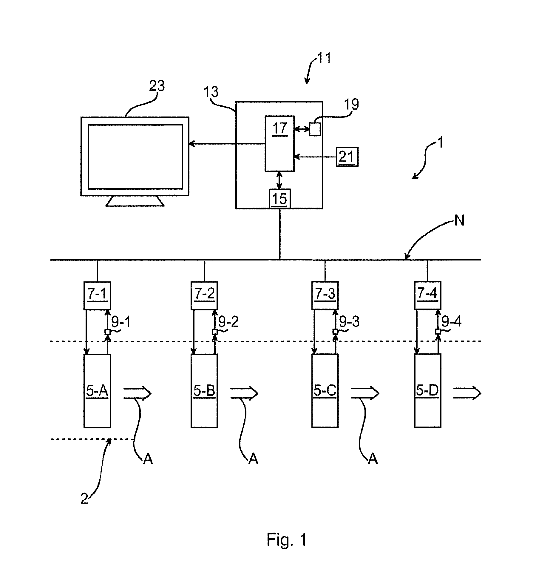
[0034]FIG. 1 schematically shows an example of a control system 1 for monitoring and controlling an industrial process 3. The industrial process 3 usually involves various process steps carried out by one or more process component 5-A, 5-B, 5-C and 5-D. The process flow according to the example of FIG. 1 is in a direction from left to right, as indicated by arrows A.

[0035]An industrial process is to be understood to mean ...


PUM


Abstract

A method of monitoring and controlling an industrial process associated with a plurality of process variables by a control system including displaying a set of process related images which are user-selected on a display device of the control system, each process related image of the set of process related images being associated with a process variable of the plurality of process variables; receiving process variable data of the plurality of process variables while the step of displaying is carried out, and when process variable data is received indicating that a process variable has a status value outside a predetermined accepted range; and displaying, on the display device, a process related image which is associated with the process variable with the status value outside the predetermined accepted range, receiving an input command for controlling the process variable, and controlling the process variable based on the input command.

Description

CROSS-REFERENCE TO RELATED APPLICATIONS[0001]The present application claims priority of European patent application No. 11181176.6 filed on Sep. 14, 2011, the content of which is incorporated herein by reference.FIELD OF THE INVENTION[0002]The present disclosure generally relates to monitoring and controlling an industrial process and in particular to a method and a system for such purposes.BACKGROUND OF THE INVENTION[0003]Industrial control systems, process control systems, Supervisory Control and Data acquisition (SCADA) systems and the like have displays for displaying a graphic diagram of the industrial system to operators monitoring the industrial system.[0004]Operators may thereby be able to recognize an alarm or a trend in the industrial system and, as a result, take measures to solve the problem giving rise to the alarm or trend.[0005]Existing industrial system control systems have several drawbacks, including having user interfaces which are non-intuitive and which provide ...

Claims


Application Information

Patent Timeline
Patent Type & Authority Patents(United States)
IPC IPC(8): G05B15/00G05B19/418G05B23/02
CPCG05B19/41845G05B23/0232G05B2219/32404Y02P90/02
Inventor TIMSJO, SUSANNEOLAUSSON, MARTINPEI-BREIVOLD, HONGYU
Owner ABB (SCHWEIZ) AG
Why Eureka
Try Eureka