Very high efficiency uninterruptible power supply

a power supply and high efficiency technology, applied in the direction of emergency power supply arrangements, transportation and packaging, dc source parallel operation, etc., can solve the problems of uninterruptible power supply and energy cost increase, and achieve the effect of reducing cost and weigh

Inactive Publication Date: 2015-12-01
PARKER INTANGIBLES LLC
View PDF25 Cites 2 Cited by
  • Summary
  • Abstract
  • Description
  • Claims
  • Application Information

AI Technical Summary

Benefits of technology

[0003]The best utility of the invention is found in on-line uninterruptible power supplies (UPS) used in data centers, banks, hospitals, air traffic control and other applications where power availability and quality are critical. The current global market for UPS systems is $7.2B and is projected to reach $10B by 2015. It is estimated that a 1 MW high-availability data center can consume $20,000,000,of electricity over its lifetime. Currently on-line UPS systems have input rectifier and output bridge power conversion efficiencies of 96% (each) or total throughput efficiencies of 92%. This equates to $1,600,000 of electricity lost in power conversion waste heat over the life of one 1 MW system. A UPS system based on the invention would have less than half the power conversion losses of the highest performance state-of-the-art machines now on the market and would also have significant reductions in cost, weight, size and installation site heat removal requirements.

Problems solved by technology

As the power conversion industry matures and the cost of energy increases, manufacturers of uninterruptible power supplies (UPS), renewable energy power converters and motor drives have been challenged by market demands to provide products with higher conversion efficiencies, higher reliability and lower cost per kilowatt.

Method used


Image

  • Very high efficiency uninterruptible power supply
  • Very high efficiency uninterruptible power supply
  • Very high efficiency uninterruptible power supply

Examples


Embodiment Construction

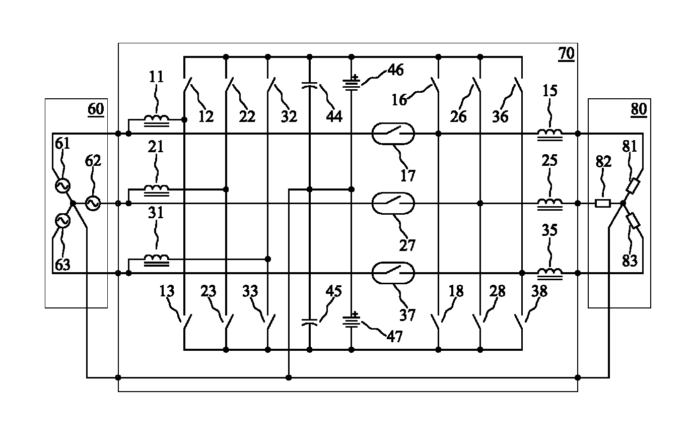
[0007]FIG. 1 is an electrical schematic which illustrates the invention in its simplest possible form. Positive DC source 6, AC source 7, Negative DC source 8, and load 10 are all referenced to and have a common connection to arbitrary neutral 0. Switch pole 4 and switch throws 1, 2 and 3 together form a single-pole-three-throw switch (SP3T). In practice, the SP3T switch function would be configured as a high speed semiconductor switching matrix. Sources 6, 7 and 8 connect to switch throws 1, 2 and 3, respectively. Switch pole 4 connects to the switched end of inductor 5. The load end of inductor 5 is connected to load 10 at circuit connection point 9. The inductor and therefore the load current are illustrated by arrow 50. If AC source 7 were replaced with a short circuit the topology would be a prior-art, three level neutral point clamp (3LNPC) power converter topology.

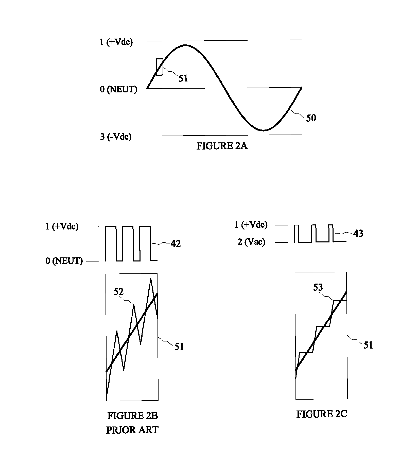
[0008]FIG. 2B illustrates the performance of a prior art, three level neutral point clamp DC-to-AC power converte...


PUM


Abstract

The invention is an electrical power conversion topology. The preferred embodiment is as a three-phase, on-line Uninterruptible Power Supply (UPS). The desired AC output voltage waveform is formed on each output line or phase of the UPS, using pulse modulation techniques and a smoothing output filter inductor. A semiconductor switching matrix is used to switch the power converter side of each output filter inductor between three voltage potentials, a positive battery potential, a negative battery potential and a third intermediate and varying AC potential synchronized with the desired output voltage. The invention potentially provides the same performance as that of a multi-level inverter topology approaching an infinite number of DC levels.

Description

BACKGROUND OF THE INVENTION[0001]As the power conversion industry matures and the cost of energy increases, manufacturers of uninterruptible power supplies (UPS), renewable energy power converters and motor drives have been challenged by market demands to provide products with higher conversion efficiencies, higher reliability and lower cost per kilowatt. Thirty years ago many large commercial power converters were based on low frequency SCR (silicon controlled rectifier) and thyristor based topologies. These were replaced by 2-level, half-bridge, higher frequency, pulse modulated IGBT (insulated gate bipolar transistor) based topologies. In the last few years, the industry has seen the emergence of 3-level neutral point clamp, and higher level IGBT based topologies previously used only in high power, medium-voltage applications. The invention potentially approaches the same performance as that of a multi-level inverter topology with an infinite number of DC levels. When compared to...

Claims


Application Information

Patent Timeline
Patent Type & Authority Patents(United States)
IPC IPC(8): H02J4/00H02M5/297H02J9/06H02M5/458
CPCH02M5/297H02J9/062H02M5/4585Y10T307/696Y10T307/406Y10T307/549H02J2009/063H02J9/063
Inventor WEST, RICHARD TRAVIS
Owner PARKER INTANGIBLES LLC
Why Eureka
Try Eureka