
Signal component rejection

a signal component and component technology, applied in the direction of pulse manipulation, pulse technique, electrical apparatus, etc., can solve the problems of reducing the intermodulation between signal components of output signals, affecting the signal quality and performance of wireless devices, and unwanted in-band distortion

Active Publication Date: 2015-12-01
QUALCOMM INC
View PDF33 Cites 5 Cited by
  • Summary
  • Abstract
  • Description
  • Claims
  • Application Information

AI Technical Summary

Benefits of technology

The patent is about a way to reduce intermodulation between signal components in an output signal. This is accomplished by suppressing and rejecting certain signal components in the output signal. This can lead to a lower level of intermodulation, which can help improve the quality of the output signal. This technique can be particularly useful when using non-linear amplifiers.

Problems solved by technology

Some of the signal components of the output signal may intermodulate with each other to cause unwanted in-band distortion.
Such intermodulation between the signal components of the output signal may degrade the adjacent channel leakage-power ratio (ACLR) and the error vector magnitude (EVM) of the signal transmitter of the computing device.
For example, the degraded ACLR and EVM caused by such in-band distortion may result in a drop in signal quality and performance at a wireless device (e.g., cause a signal-to-noise ratio (SNR) to drop below an acceptable level).
However, such systems may only reject a specific harmonic (e.g., a third order harmonic) and may not be flexible enough to cancel multiple desired higher-order harmonics.
Thus, existing systems and methods of reducing in-band distortion may add complexity, cost, and / or power consumption to a device.

Method used


Image

  • Signal component rejection
  • Signal component rejection
  • Signal component rejection

Examples


Embodiment Construction

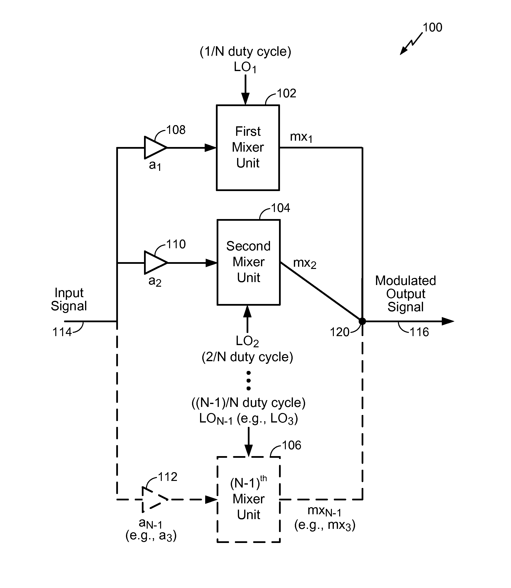
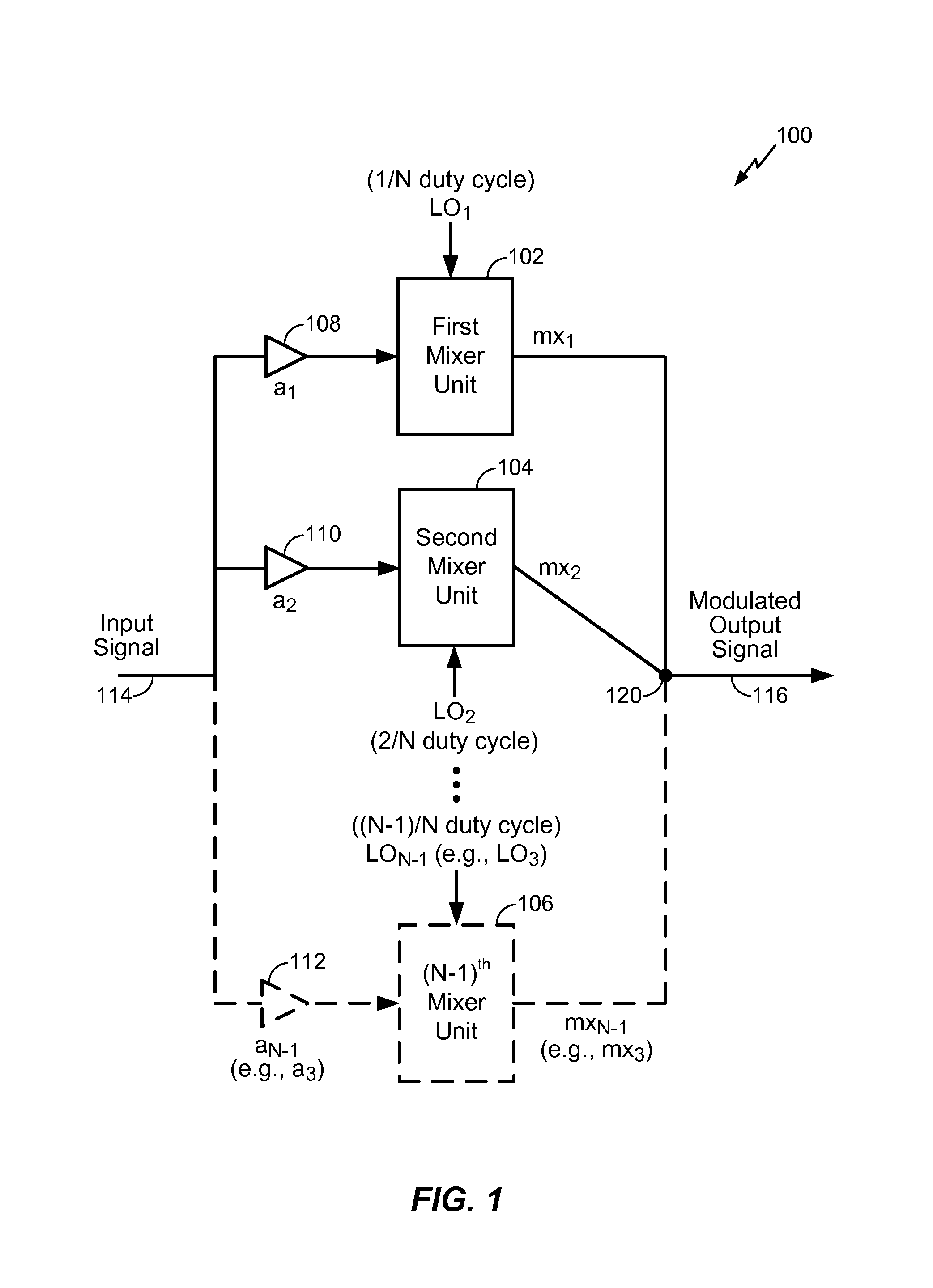
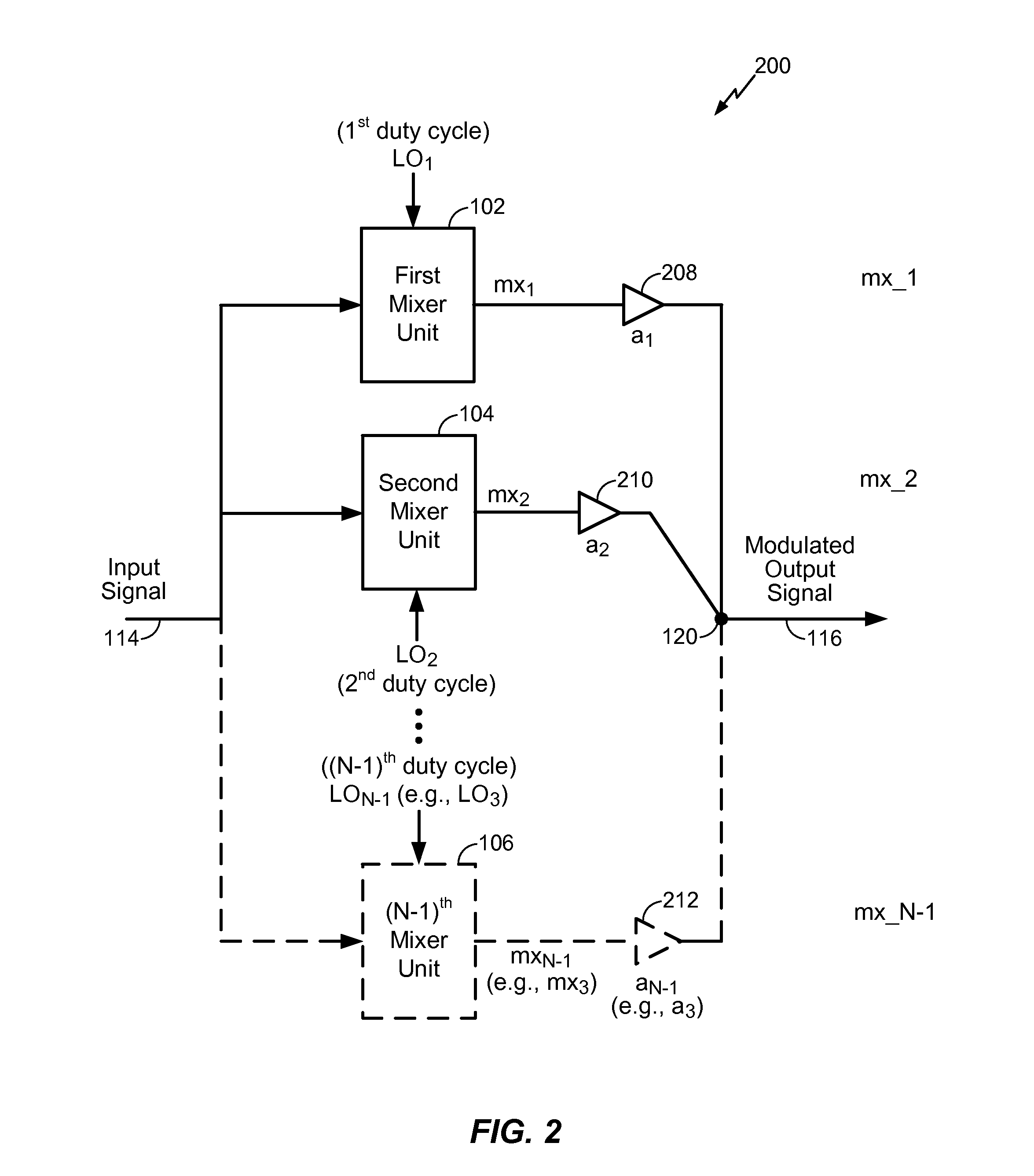
[0016]Referring to FIG. 1, a particular embodiment of a device operable to perform signal component rejection is depicted and generally designated 100. As used herein, “suppression” and “rejection” of a signal component (e.g., a particular harmonic component) may be interchangeable and may refer to a signal processing operation by which a signal component that is present in an input signal is entirely or substantially removed with respect to an output signal. The device 100 includes N−1 mixer units and N−1 scaling units, where N is an integer greater than 2. To illustrate, when N is 3, the device 100 has two mixer units including a first mixer unit 102 and a second mixer unit 104. When N is greater than 3, the device 100 may have three or more mixer units. For example, when N is 4, the device 100 includes the first mixer unit 102, the second mixer unit, 104, and the third (i.e., (N−1)th) mixer unit 106. As another example, when N is 5, the device 100 has four mixer units including t...


PUM


Abstract

A method includes providing a first local oscillator signal having a first duty cycle to a first mixer unit and providing a second local oscillator signal having a second duty cycle to a second mixer unit. At least one of the first duty cycle or the second duty cycle is greater than fifty percent. A frequency of the first local oscillator signal approximately equals a frequency of the second local oscillator signal. The method may also include generating a modulated output signal based on an output signal of the first mixer unit and based on an output signal of the second mixer unit.

Description

I. FIELD[0001]The present disclosure is generally related to signal component rejection.II. DESCRIPTION OF RELATED ART[0002]Advances in technology have resulted in smaller and more powerful computing devices. For example, there currently exist a variety of portable personal computing devices, including wireless computing devices, such as portable wireless telephones, personal digital assistants (PDAs), and paging devices that are small, lightweight, and easily carried by users. More specifically, portable wireless telephones, such as cellular telephones and internet protocol (IP) telephones, can communicate voice and data packets over wireless networks. Further, many such wireless telephones include other types of devices that are incorporated therein. For example, a wireless telephone can also include a digital still camera, a digital video camera, a digital recorder, and an audio file player. Also, such wireless telephones can process executable instructions, including software ap...

Claims


Application Information

Patent Timeline
Patent Type & Authority Patents(United States)
IPC IPC(8): H04B1/04H01Q11/12H03D7/18H03D7/16H03K5/13H03K5/1252
CPCH03K5/1252H03D7/165H03K5/13H03D7/18H03D2200/0086
Inventor LIN, SAIHUABROCKENBROUGH, ROGER
Owner QUALCOMM INC
Learn More