Display device and electronic apparatus

a display device and electronic equipment technology, applied in electrical equipment, instruments, pictoral communication, etc., can solve the problems of deterioration of light intensity input from light guiding plate to liquid crystal panel, and achieve the effect of suppressing deterioration of image quality

Active Publication Date: 2015-12-01
138 EAST LCD ADVANCEMENTS LTD
View PDF25 Cites 0 Cited by
  • Summary
  • Abstract
  • Description
  • Claims
  • Application Information

AI Technical Summary

Benefits of technology

[0010]An advantage of some aspects of the invention is to provide a display device which can suppress a deterioration in an image quality in a second mode, even when a difference in brightness between the first mode in which a first image and a second image which are divided based on the time the images are captured or optically are displayed and a second mode in which an image is displayed without being divided based on the time the images is captured or optically is compressed, and an electronic apparatus.
[0012]In this case, at least the light emitting intensity of the second light emitting element row is controlled in the second mode which the image is displayed without being divided based on the time or optically, the average of light emitting intensity of the light sources is set to be smaller than the first mode in which a first image and a second image which are divided based on the time or optically each other are displayed. For this reason, it is possible to compress a difference in brightness between the images which are divided in the first mode and the image in the second mode. In addition, each of the light emitting intensity of light emitting elements in the light emitting element row is the same since the light emitting intensity is controlled in each light emitting element row in the second mode. Accordingly, distribution of an intensity of light input from the light guiding plate to an optical panel does not deteriorate. Therefore, it is possible to suppress a deterioration in an image quality in the second mode.
[0016]According to another aspect of the invention, there is provided a display device which includes an optical panel including an image display area; a backlight unit including a light guiding plate which disposed to be overlapped to the optical panel, and light sources which are arranged at a plurality of side surfaces of the light guiding plate; a first mode in which a first image and a second image which are divided based on the time or optically each other are displayed in the image display area; and a second mode which a third image is displayed without being divided based on the time or optically in the image display area, in which the light source includes a first light emitting element row which disposed along a first side surface among the plurality of the side surfaces, a second light emitting element row which disposed along a second side surface which is different from the first side surface among the plurality of the side surfaces, a third light emitting element row which disposed along a third side surface facing the first side surface and a fourth light emitting element row which disposed along a fourth side surface facing the second side surface, and in which a second average of light emitting intensity of the light sources in the second mode is lower than a first average of light emitting intensity of the light sources in the first mode by controlling at least the light emitting intensities of the second light emitting element row and the fourth light emitting element row. In this case, at least the light intensities of the second light emitting element row and the fourth light emitting row are controlled, and the average of light emitting intensity of the light sources is decreased in the second mode compared to the first mode. For this reason, it is possible to compress a difference in brightness between images which are divided in the first mode and an image in the second mode. In addition, each of the light emitting intensity of light emitting elements in the light emitting element row is the same since the light emitting intensity is controlled in each light emitting element row in the second mode. Accordingly, distribution of an intensity of light input to an optical panel from a light guiding plate does not deteriorate. Therefore, it is possible to suppress a deterioration in an image quality in the second mode.
[0022]According to any of the aspects, in the first light emitting element row and the second light emitting element row, a first emission optical axis of light emitting elements on the first light emitting element row and a second emission optical axis of light emitting elements on the second light emitting element row may be deviated in an extending direction of the first side surface, and the light guiding plate may be formed with diffusing patterns of which a diffusing degree is increased toward a position away from a position which is close to light emitting element on the first light emitting element row in a region which is overlapped with the first emission optical axis when planarly viewed, and may be formed with diffusing patterns of which a diffusing degree is increased toward a position away from a position which is close to light emitting element on the second light emitting element row in a region which is overlapped with the second emission optical axis when planarly viewed. In this case, in the second mode, it is possible to maintain a state in which luminance distribution is appropriate even when the light emitting intensity of the first light emitting element row and the second light emitting element row facing across the light guiding plate are changed.

Problems solved by technology

However, as in the technology which is disclosed in FIG. 2 in JP-A-2006-228723, in a technology in which a plurality of light emitting elements are alternately turned on when displaying a 2D image, since a light emitting element in an OFF state is interposed between light emitting elements which are ON states, a distribution of an intensity of light input to a light guiding plate becomes largely different in places, and as a result, there is a problem in that the distribution of an intensity of light input from the light guiding plate to a liquid crystal panel deteriorates, and an image quality remarkably deteriorates.
The above described problem similarly occurs when the first image and the second image are optically divided, and are displayed at the same time in an image display area using different polarization in a first mode, and a 3D image is displayed by the first and second images.
In addition, the above problem similarly occurs when the first image formed by the 2D image which is displayed in the image display area is viewed by a specific person in the first mode, and the second image formed by the 2D image which is displayed in the image display area is viewed by a different person.

Method used


Image

  • Display device and electronic apparatus
  • Display device and electronic apparatus
  • Display device and electronic apparatus

Examples


first embodiment

Entire Configuration

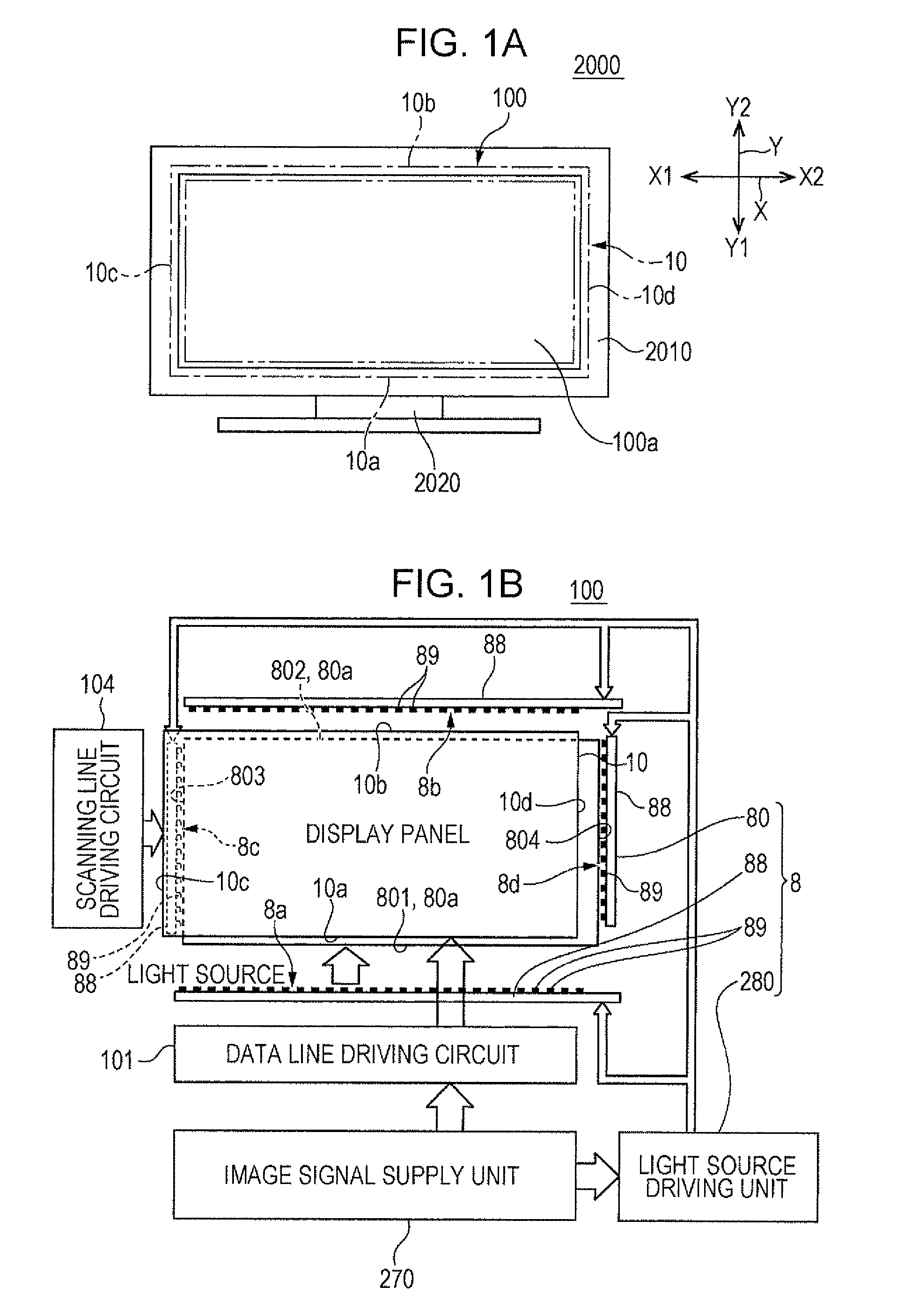
[0037]FIGS. 1A and 1B are explanatory diagrams of a liquid crystal television (electronic apparatus) including a liquid crystal display device according to a first embodiment of the invention, and in which FIG. 1A is an explanatory diagram which schematically illustrates an appearance of a liquid crystal television, and FIG. 1B is a block diagram which illustrates an electrical configuration of the liquid crystal display device, respectively.

[0038]An electronic apparatus 2000 which is illustrated in FIG. 1A is a liquid crystal television, and includes a liquid crystal display device 100, a television frame 2010, and a television stand 2020, or the like. The liquid crystal display device 100 includes a transmission type liquid crystal panel 10, an image signal supply unit 270 which supplies an image signal to the liquid crystal panel 10, and a backlight unit 8 which supplies illumination light to the liquid crystal panel 10. In addition, the liquid crystal display...

modification example of first embodiment

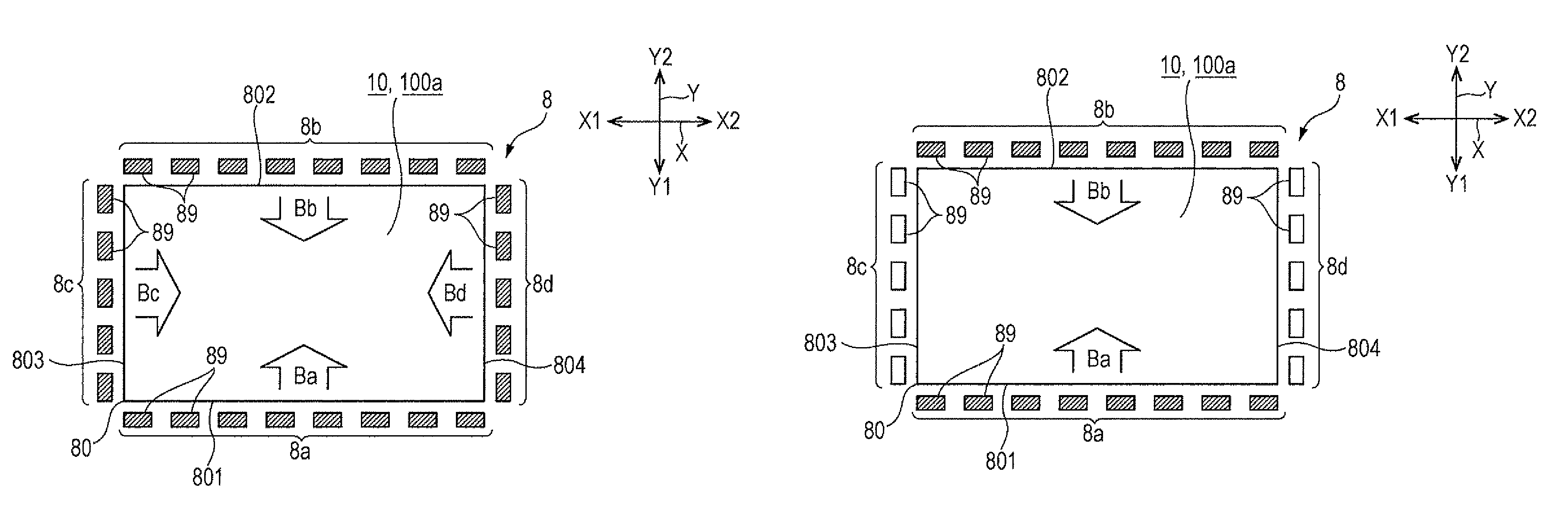
[0066]According to the first embodiment, in the light guiding plate 80, the first set of side surfaces facing each other in one direction (Y axis direction) are side surfaces 801 and 802, and the second set of side surfaces facing each other in the other direction (X axis direction) are side surfaces 803 and 804, however, it may be a configuration in which the first set of side surfaces are side surfaces 803 and 804, and the second set of side surfaces are side surfaces 801 and 802. According to the configuration, the plurality of first light emitting elements (first light emitting element row) are the light emitting element rows 8c and 8d which are arranged along the two side surfaces 803 and 804 which belong to the first set, and the plurality of second light emitting elements (second light emitting element row) are the light emitting element rows 8a and 8b which are arranged along the two side surfaces 801 and 802 which belong to the second set. Accordingly, in the 3D mode, the f...

second embodiment

[0068]FIGS. 5A and 5B are explanatory diagrams which illustrate lighting patterns of light emitting elements 89 in a liquid crystal display device 100 according to a second embodiment of the invention. FIG. 5A is an explanatory diagram which illustrates an ON state of the light emitting elements 89 in a 3D mode, and FIG. 5B is an explanatory diagram which illustrates an ON state of the light emitting elements 89 in a 2D mode, respectively. In addition, since a basic configuration according to the embodiment is the same as that in the first embodiment, shared portions are given the same reference numerals, and descriptions thereof will be omitted. In addition, in FIGS. 5A and 5B, light emitting elements 89 which are turned on are denoted by slanted lines.

[0069]According to the first embodiment, the light emitting elements 89 are arranged along the four side surfaces 801, 802, 803, and 804 of the light guiding plate 80, however, according to the embodiment, as illustrated in FIGS. 5A ...


PUM


Abstract

A display device includes a backlight unit, a light guiding plate which is overlappingly arranged on an optical panel, light emitting elements which are arranged on the side surface of the light guiding plate, and a light source driving unit which drives the light emitting elements. The light source driving unit intermittently turns on all of the light emitting elements when displaying a 3D image on the optical panel. In contrast to this, when displaying a 2D image on the optical panel, each light emitting intensity of the light emitting elements in a part of rows is set to be the same as that in a 3D mode, and each light emitting intensity of the light emitting elements in a part of rows other than that is set to be lower than that in the 3D mode.

Description

BACKGROUND[0001]1. Technical Field[0002]The present invention relates to a liquid crystal display device in which a first mode displaying a first image and a second image which are divided based on the time the images are captured based on the time the images are captured or optically in an image display area, and a second mode displaying an image without dividing the image based on the time the image is captured or optically in the image display area are executed, and an electronic apparatus including the liquid crystal display device.[0003]2. Related Art[0004]A liquid crystal display device includes a liquid crystal panel having an image display area, and a backlight unit which supplies illumination light to the liquid crystal panel, and the backlight unit includes a light guiding plate which is overlappingly arranged at a side opposite to an output side of display light with respect to the liquid crystal panel, a light source which is arranged at the side surface of the light gui...

Claims


Application Information

Patent Timeline
Patent Type & Authority Patents(United States)
IPC IPC(8): H04N13/04G09G3/34G09G3/36H04N13/00
CPCH04N13/0452G09G3/3406G09G3/36H04N13/00H04N13/0434H04N13/0438H04N13/0454H04N13/0429G09G2320/062G09G2320/0646G09G2320/04G09G2320/0209G09G2320/0233H04N13/332H04N13/337H04N13/341H04N13/356H04N13/359
Inventor MOMOSE, YOICHIURANO, NOBUTAKATAIRA, JUNICHI
Owner 138 EAST LCD ADVANCEMENTS LTD
Why Eureka
Try Eureka