Image forming apparatus and image forming method

a technology of image forming and apparatus, applied in the field of image forming apparatus and image forming method, can solve the problems of large computational cost, long processing time, and inability to obtain high compression ratio for other images, and achieve the effect of suppressing the reduction of image quality

Inactive Publication Date: 2010-06-01
CANON KK
View PDF10 Cites 3 Cited by
  • Summary
  • Abstract
  • Description
  • Claims
  • Application Information

AI Technical Summary

Benefits of technology

[0012]The present invention has been made in consideration of the above situation, and has a feature to suppress a reduction in image quality which may result from image processing and re-coding when a decoded image is processed and re-coded.

Problems solved by technology

However, high compression ratios cannot be obtained for other images.
Therefore, such an apparatus is not suitable for outputting an image to a color printer or displaying an image on a display or the like.
Accordingly, a large computational cost and a long processing time are needed to perform processing.
Therefore, such an apparatus is not applicable to a digital camera.

Method used


Image

  • Image forming apparatus and image forming method
  • Image forming apparatus and image forming method
  • Image forming apparatus and image forming method

Examples


first embodiment

[0034]A first embodiment of the present invention will be described with reference to FIGS. 1 to 3E.

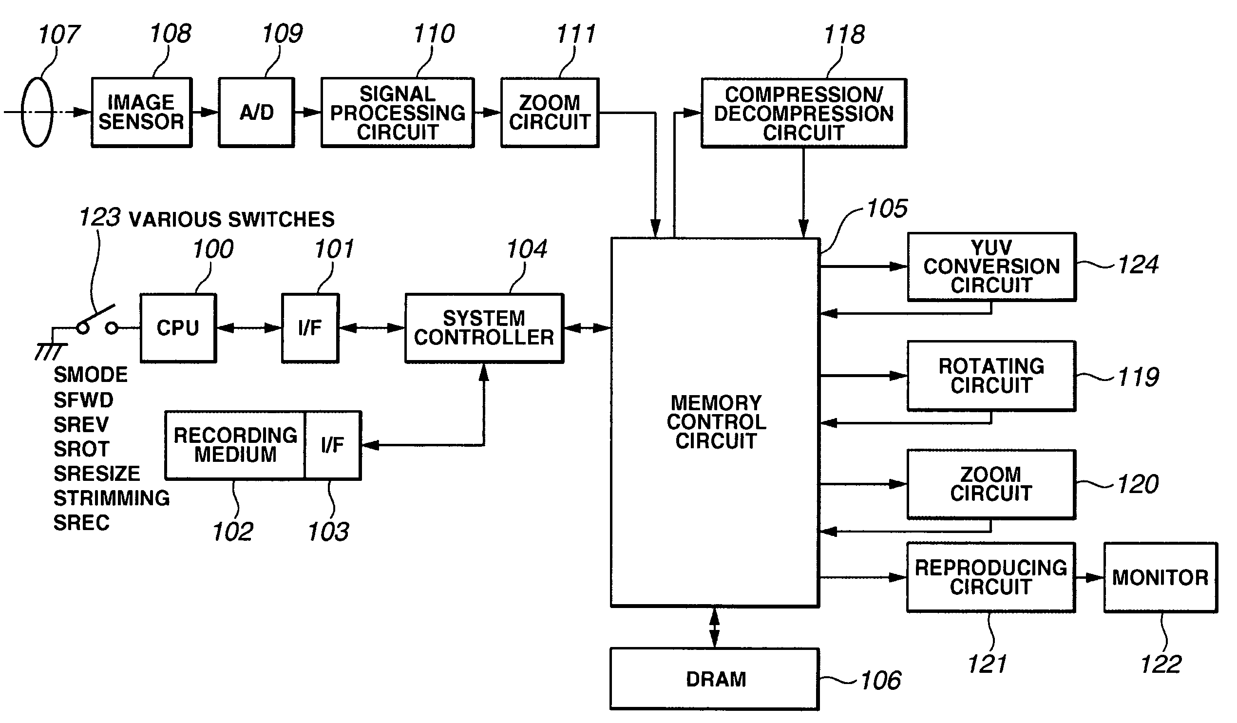
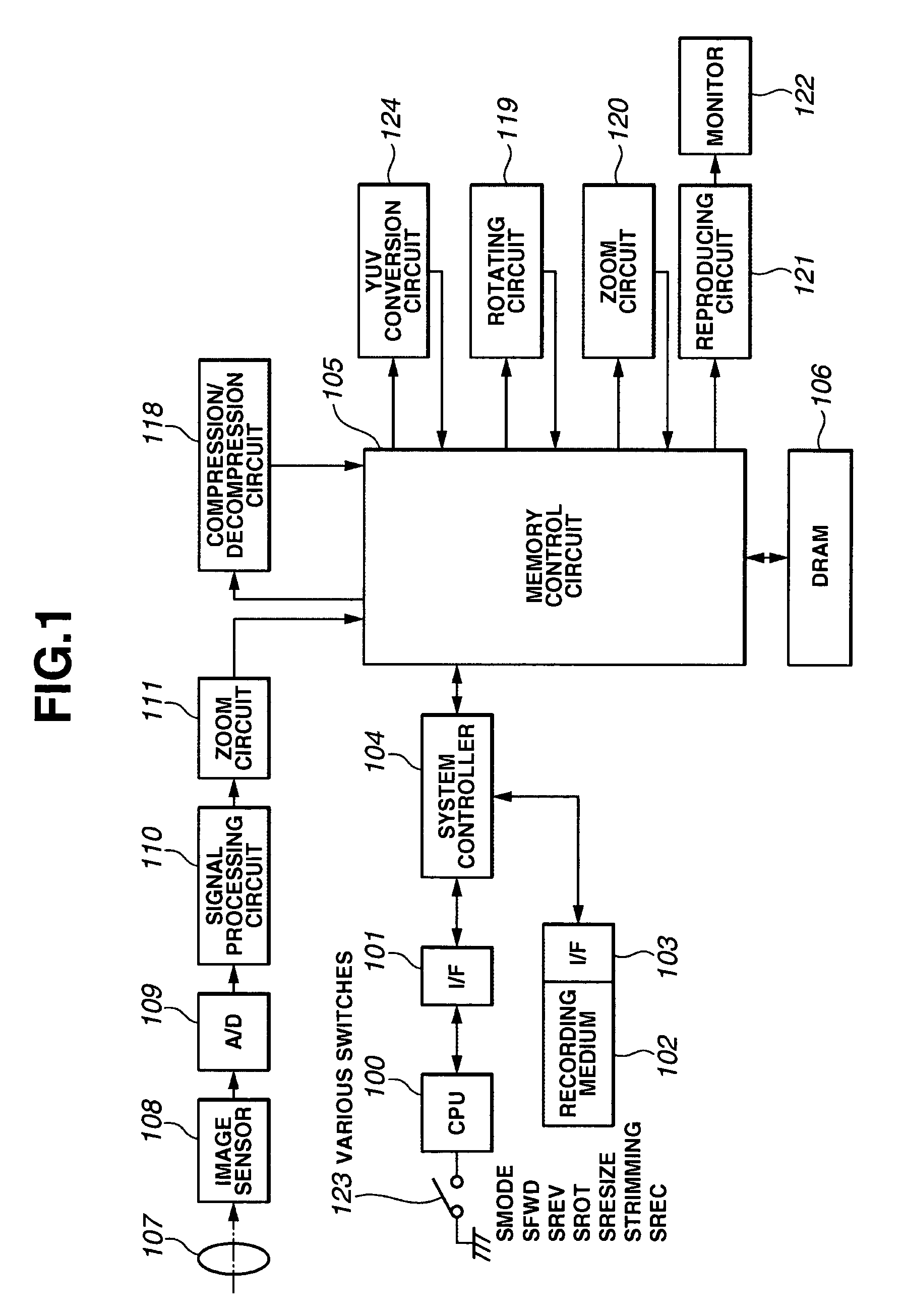
[0035]FIG. 1 is a block diagram showing a system configuration of an image capture apparatus according to the first embodiment. Referring to FIG. 1, reference numeral 100 denotes a central processing unit (CPU) for controlling the entire system. Reference numeral 101 denotes an interface circuit (I / F) for the CPU 100, reference numeral 102 denotes a storage medium such as a memory card, and reference numeral 103 denotes an interface circuit (I / F) for the storage medium 102. Reference numeral 104 denotes a system controller for executing sequential control of the system or control of bus arbitration or the like. Reference numeral 106 denotes a dynamic random access memory (DRAM) for storing image data, a program, or the like. A memory control circuit 105 is a direct memory access controller (DMAC) for DMA-transferring JPEG compressed data stored on the storage medium 102 to the DRAM 10...

second embodiment

[0069]Next, a second embodiment of the present invention will be described with reference to FIG. 4.

[0070]A basic system configuration of an image forming method of the second embodiment is similar to that of the first embodiment shown in FIGS. 1 and 2, and therefore, the description of the second embodiment includes references to these figures.

[0071]The second embodiment is applied to a digital camera having the function of rotating and recompressing a reproduced image.

[0072]The image forming method of the second embodiment will be described below in detail.

[0073]A case of rotating JPEG-compressed data of YUV422 data format will be described.

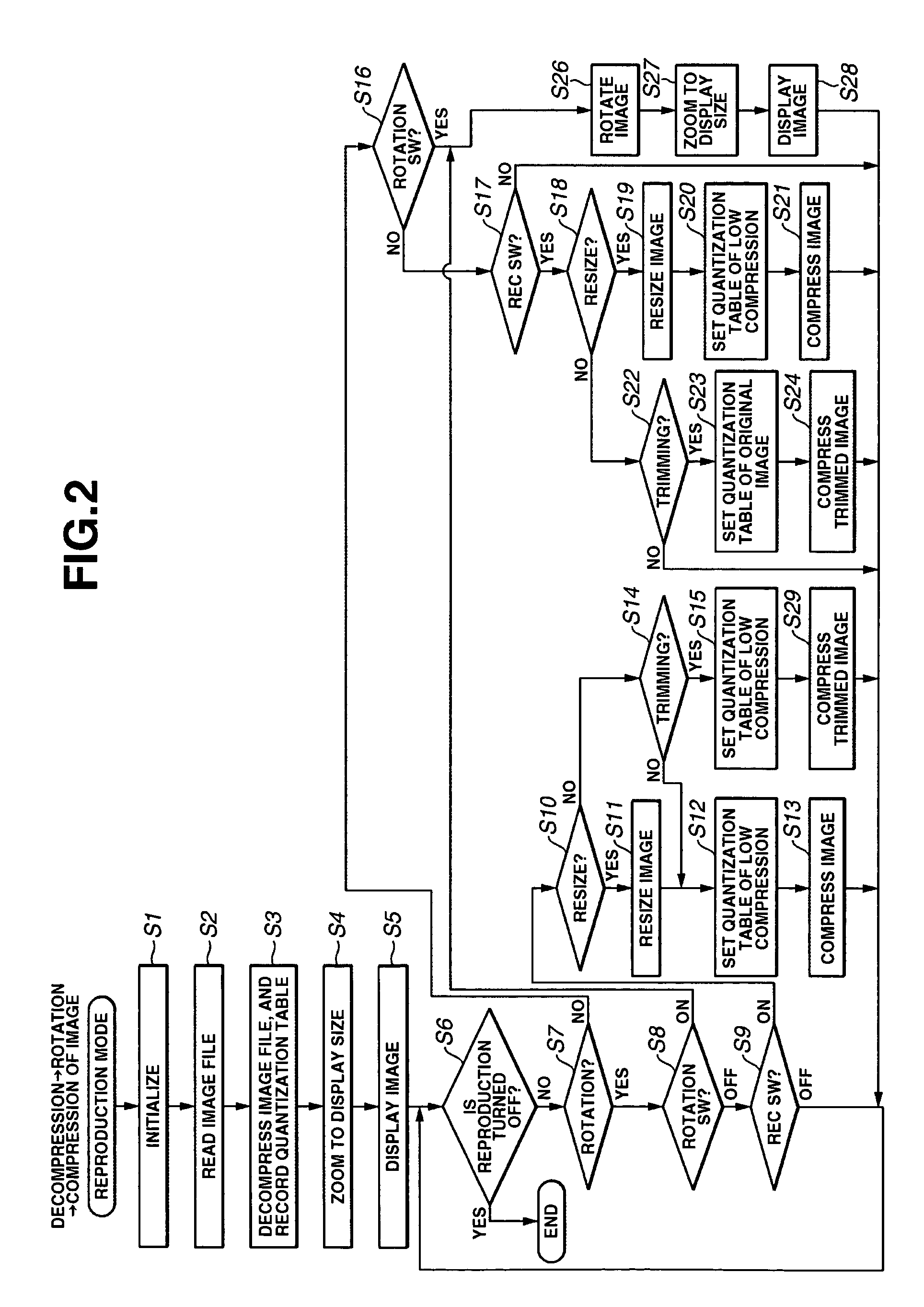
[0074]A difference from the first embodiment is the method of setting a quantization table providing a low compression ratio in step S12 of FIG. 2.

[0075]The detail of step S12 in the present embodiment is described with reference to FIG. 4.

[0076]In step S100, a quantization table providing a lowest compression ratio among a plurality of quantiz...

third embodiment

[0083]Next, a third embodiment of the present invention will be described.

[0084]A basic system configuration of an image forming method of the third embodiment is similar to that of the first embodiment shown in FIGS. 1 and 2, and therefore, the description of the third embodiment includes references to these figures.

[0085]According to the third embodiment, the image forming method is applied to a digital camera which has the function of resizing and recompressing a reproduced image.

[0086]The image forming method of the third embodiment will be described below in detail.

[0087]A case of resizing JPEG-compressed data of YUV422 data format will be described.

[0088]As in the first embodiment, the process proceeds from step S1 through step S7, in which image data stored in the DRAM 106 having the number of pixels corresponding to the liquid crystal monitor 122 is supplied to the reproducing circuit 121. The reproduced image is then displayed on the liquid crystal monitor 122.

[0089]In step...


PUM


Abstract

An image forming apparatus and method capable of decompressing and compressing image data. More specifically, the apparatus and method include decompressing first compressed image data, processing the decompressed image data, selecting from among a plurality of quantization tables a quantization table providing a compression ratio lower than a compression ratio of the first compressed image data, and compressing the processed image data.

Description

BACKGROUND OF THE INVENTION[0001]1. Field of the Invention[0002]The present invention relates to an image forming apparatus and an image forming method that are capable of decompressing and compressing image data.[0003]2. Description of the Related Art[0004]Some conventional image processing apparatuses, such as digital cameras, have a trimming function of cutting a part of an image compressed and recorded in JPEG (Joint Photographic Experts Group) format, and recording the cut image.[0005]In addition, some conventional image processing apparatuses have a function of rotating an image with respect to photographed image data so that the photographed image data can be displayed in a correct orientation according to a posture state taken at the time of photography recorded together with the photographed image data. Furthermore, some conventional image processing apparatuses are capable of applying zoom processing to an image so as to facilitate the entire image to be displayed even aft...

Claims


Application Information

Patent Timeline
Patent Type & Authority Patents(United States)
IPC IPC(8): G06K9/36G06K9/46
CPCH04N1/00167H04N1/333H04N1/3872H04N1/3877H04N19/154H04N19/172H04N19/60H04N19/124H04N19/146H04N2101/00H04N2201/33357
Inventor SATO, YOSHINOBU
Owner CANON KK
Why Eureka
Try Eureka