Image forming apparatus and image forming method
a technology of image forming and apparatus, applied in the field of image forming apparatus and image forming method, can solve the problems of large computational cost, long processing time, and inability to obtain high compression ratio for other images, and achieve the effect of suppressing the reduction of image quality
- Summary
- Abstract
- Description
- Claims
- Application Information
AI Technical Summary
Benefits of technology
Problems solved by technology
Method used
Image
Examples
first embodiment
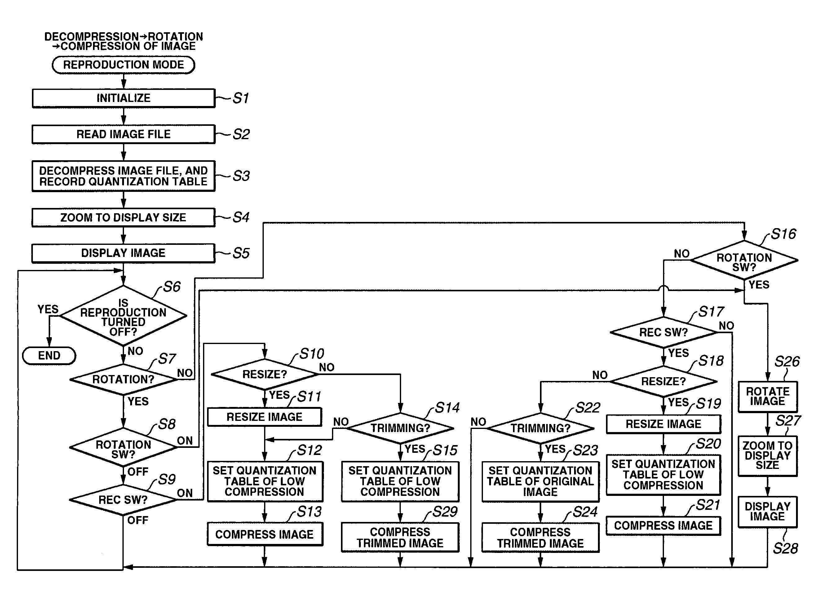
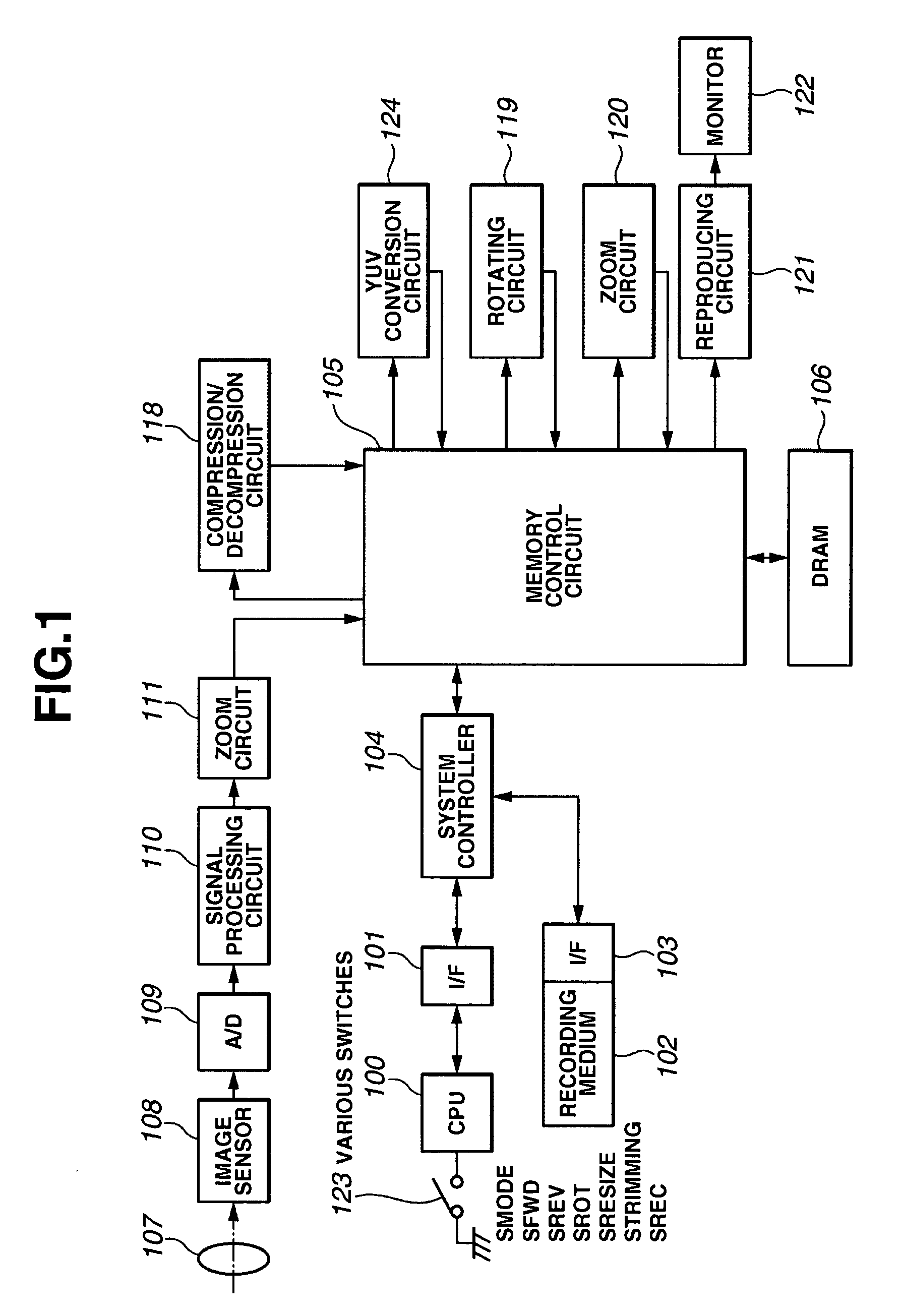
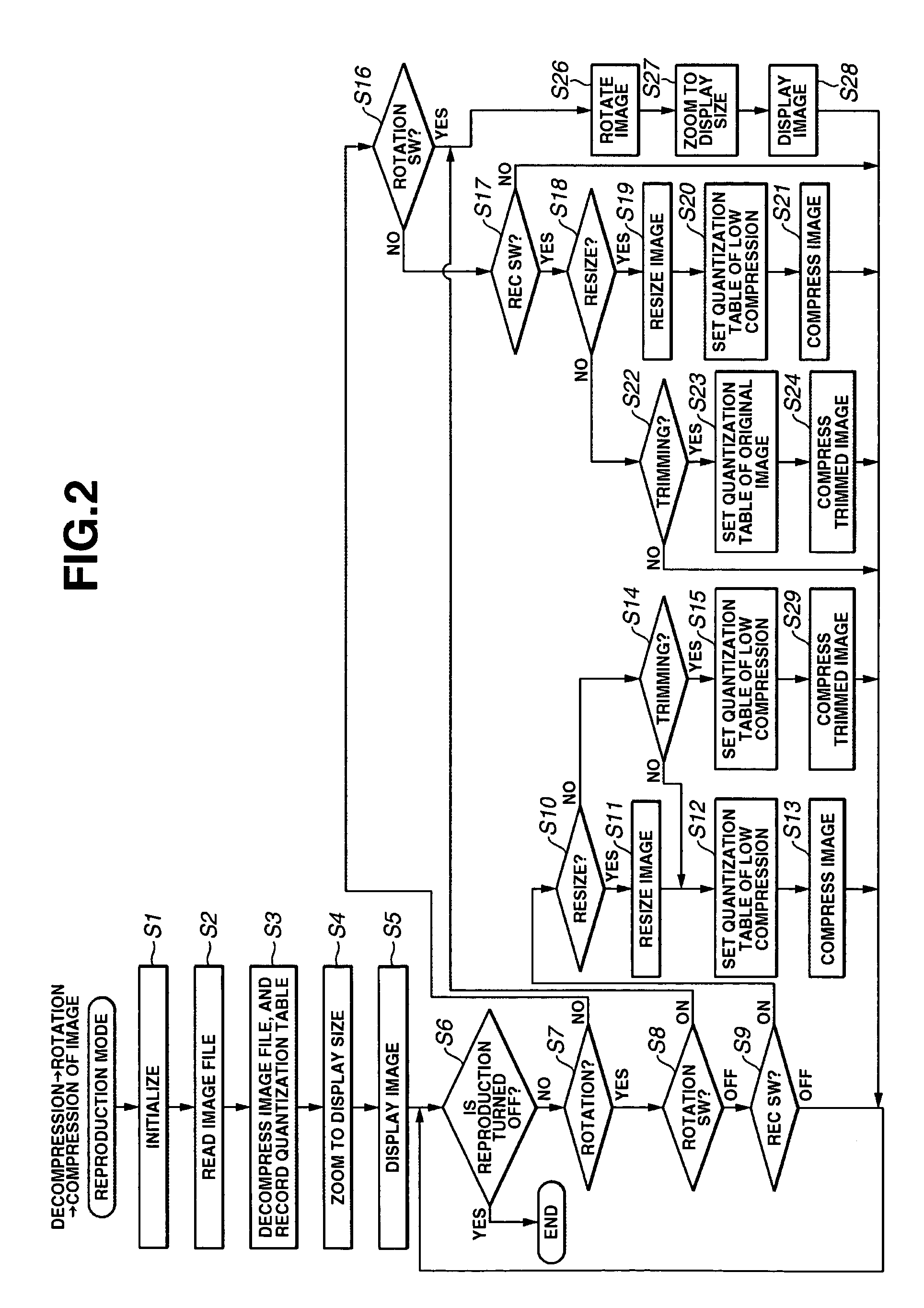
[0033] A first embodiment of the present invention will be described with reference to FIGS. 1 to 3E.
[0034]FIG. 1 is a block diagram showing a system configuration of an image capture apparatus according to the first embodiment. Referring to FIG. 1, reference numeral 100 denotes a central processing unit (CPU) for controlling the entire system. Reference numeral 101 denotes an interface circuit (I / F) for the CPU 100, reference numeral 102 denotes a storage medium such as a memory card, and reference numeral 103 denotes an interface circuit (I / F) for the storage medium 102. Reference numeral 104 denotes a system controller for executing sequential control of the system or control of bus arbitration or the like. Reference numeral 106 denotes a dynamic random access memory (DRAM) for storing image data, a program, or the like. A memory control circuit 105 is a direct memory access controller (DMAC) for DMA-transferring JPEG compressed data stored on the storage medium 102 to the DRAM ...
second embodiment
[0077] Next, a second embodiment of the present invention will be described with reference to FIG. 4.
[0078] A basic system configuration of an image forming method of the second embodiment is similar to that of the first embodiment shown in FIGS. 1 and 2, and therefore, the description of the second embodiment includes references to these figures.
[0079] The second embodiment is applied to a digital camera having the function of rotating and recompressing a reproduced image.
[0080] The image forming method of the second embodiment will be described below in detail.
[0081] A case of rotating JPEG-compressed data of YUV422 data format will be described.
[0082] A difference from the first embodiment is the method of setting a quantization table providing a low compression ratio in step S12 of FIG. 2.
[0083] The detail of step S12 in the present embodiment is described with reference to FIG. 4.
[0084] In step S100, a quantization table providing a lowest compression ratio among a plura...
third embodiment
[0091] Next, a third embodiment of the present invention will be described.
[0092] A basic system configuration of an image forming method of the third embodiment is similar to that of the first embodiment shown in FIGS. 1 and 2, and therefore, the description of the third embodiment includes references to these figures.
[0093] According to the third embodiment, the image forming method is applied to a digital camera which has the function of resizing and recompressing a reproduced image.
[0094] The image forming method of the third embodiment will be described below in detail.
[0095] A case of resizing JPEG-compressed data of YUV422 data format will be described.
[0096] As in the first embodiment, the process proceeds from step S1 through step S7, in which image data stored in the DRAM 106 having the number of pixels corresponding to the liquid crystal monitor 122 is supplied to the reproducing circuit 121. The reproduced image is then displayed on the liquid crystal monitor 122.
[...
PUM
 Abstract
Description
Claims
Application Information
 - R&D
- Intellectual Property
- Life Sciences
- Materials
- Tech Scout
- Unparalleled Data Quality
- Higher Quality Content
- 60% Fewer Hallucinations
Browse by: Latest US Patents, China's latest patents, Technical Efficacy Thesaurus, Application Domain, Technology Topic, Popular Technical Reports.
© 2025 PatSnap. All rights reserved.Legal|Privacy policy|Modern Slavery Act Transparency Statement|Sitemap|About US| Contact US: help@patsnap.com


