Method and apparatus for creating a high efficiency surface mount illumination device for projecting electromagnetic radiation at a high angle from the surface normal

a surface mount illumination and high-efficiency technology, applied in the direction of semiconductor devices for light sources, lighting and heating apparatus, fixed installations, etc., can solve the problems of large heat generation of conventional marine lamps, and achieve the effects of efficient optical projection, low cost, and efficient and cost-effectiv

Active Publication Date: 2015-12-08
DRAGONFISH TECH
View PDF6 Cites 2 Cited by
  • Summary
  • Abstract
  • Description
  • Claims
  • Application Information

AI Technical Summary

Benefits of technology

[0019]Prior marine docking lamps are used in a variety of applications including illumination of areas behind cargo trailers to provide greater visibility during low light or low-visibility conditions, e.g., nighttime. In the case of a marine vessel conventional docking lamps are mounted on the hull and angled to the front of the boat to illuminate the area ahead of the boat during low visibility conditions. Due to the high intensity requirements of the lamps, conventional marine lamps have incorporated large sources in the lamp housing which has heretofore required that the lamp body project significantly below the mounting surface. The present invention is directed to a lamp in which the projection of the lamp body below the surface is eliminated and, as such, alleviates the severe mounting requirements of conventional marine lamps.
[0022]In consideration of consumer demand for customization, the present inventors further recognized that by making the light emitting portion as thin as possible it became a simple effort to enclose it in a customized cover. The cover can be a wide variety of materials including but not limited to; aluminum, stainless steel and plastic.
[0024]It is another object of the present invention to provide a low profile surface mounted lamp for the efficient optical projection of a primary beam at an angle of approximately 60 degrees from the surface normal.
[0025]It is a further object of the present invention to provide a lower cost and more effective approach to the installation of marine docking lights.
[0027]It is yet a further object of the present invention to provide vehicle lights such as marine vessel docking lighting that are both efficient and cost effective.
[0030]Therefore, according to one embodiment of the present invention, an LED-based marine docking lamp is provided. The marine lamp includes a die cast aluminum heat sink, which may be fabricated using conventional fabrication techniques, with a flat or slightly curved back surface may be used as the mounting surface for the lamp. The heat sink removes heat from the LED and conducts the heat to the surrounding environment. A printed circuit board (PCB) assembly comprised of LED(s), drive electronics and a supporting substrate may be attached to the heat sink to provide the required thermal contact for the LED(s) to remain cool. A lens assembly is affixed above the LED(s) to efficiently collect the energy from the hemispherical emitter and compress the light into a high intensity beam. The beam strikes a secondary reflective surface which spreads the light into the required output distribution. A decorative stainless steel cover may be placed over the assembly and provides an aperture for the lens to project the light through. The docking lamp may have a thickness of less than 1 inch with a primary emission angle of 60 degrees to the mounting surface.

Problems solved by technology

As a result, conventional marine lamps produce a great amount of heat.

Method used


Image

  • Method and apparatus for creating a high efficiency surface mount illumination device for projecting electromagnetic radiation at a high angle from the surface normal
  • Method and apparatus for creating a high efficiency surface mount illumination device for projecting electromagnetic radiation at a high angle from the surface normal
  • Method and apparatus for creating a high efficiency surface mount illumination device for projecting electromagnetic radiation at a high angle from the surface normal

Examples


Embodiment Construction

[0056]As will be described herein, the present invention is directed to a surface mounted marine docking light or lamp and method of manufacturing same. However, it is appreciated that the present invention may be applicable with lights or lamps used for other applications, such as specialty lighting, home lighting, over-land vehicles, watercraft, aircraft and manned spacecraft electric cars, airplanes, helicopters, space stations, shuttlecraft, and the like.

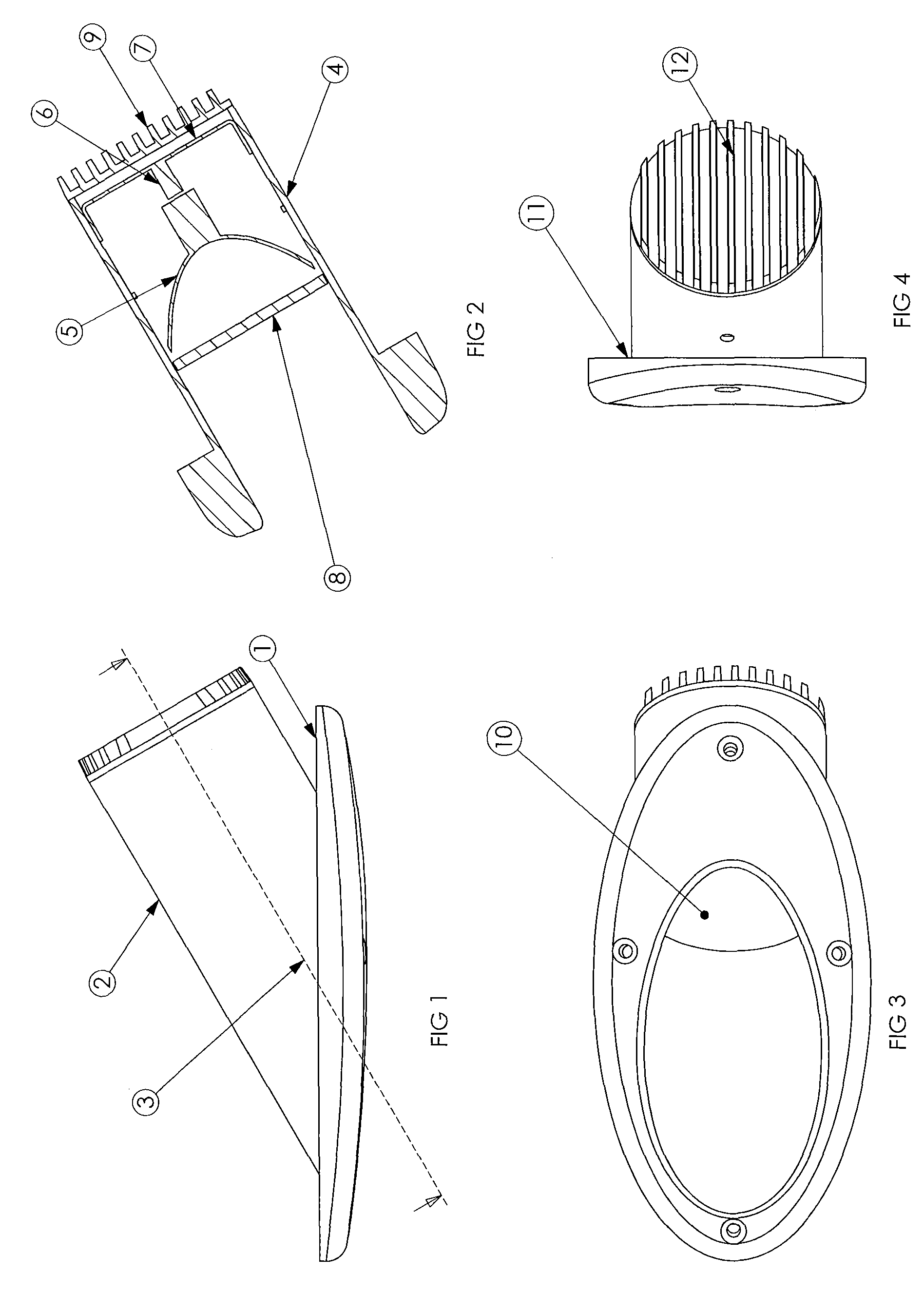
[0057]Referring now to FIG. 1, a conventional lamp often used for marine applications is shown. Conventional lamps include a flange with a flat rear back 1 which is mounted directly to the boat hull. The light source of the lamp may be incandescent, halogen, LED, gas discharge lamp or the like and is mounted within circular housing section 2 which projects backward from the mounting surface 1 at an angle of approximately 60 degrees from the normal.

[0058]As further shown in FIG. 2, light source 5 has a parabolic reflecting optic ...


PUM


Abstract

A marine lamp includes an LED and a heat sink that removes heat from the LED. A lens assembly is associated with the LED and collects the energy from the LED and compresses the light into a high intensity beam. The beam strikes a secondary reflective surface which spreads the light into a desired output distribution. In one particular application, the desired output distribution has a ring-like distribution with a primary light beam at approximately 60 degrees from mounting surface normal.

Description

CROSS-REFERENCE TO RELATED APPLICATION[0001]The present application claims the benefit of U.S. provisional application 60 / 982,955, filed Oct. 26, 2007.FIELD OF THE INVENTION[0002]The present invention relates generally to an apparatus for the projection of radiant, particularly electromagnetic energy from a surface mounted lamp at a high angle from the surface normal. More particularly, the invention is directed to the efficient generation and distribution of white light energy from a marine grade lamp for the purpose of docking marine vessels in low light environments.BACKGROUND OF THE INVENTION[0003]There are many situations where it is desirable to project high intensity beams of light for purposes of illumination. For example, automobile headlamps, flood lighting, vehicle reverse lamps, search lamps and the like. In certain cases it is required that the high intensity beams be projected at a high angle from the emission surface. For example trailer sidewall illumination lamps, m...

Claims


Application Information

Patent Timeline
Patent Type & Authority Patents(United States)
IPC IPC(8): F21V3/00F21V29/83B60Q1/02B63B45/02F21S8/10F21V5/00F21V29/00F21V29/74F21V7/00F21V5/04F21V5/02F21W107/20F21Y101/02
CPCF21V29/004B60Q1/02B63B45/02F21S48/328F21V5/02F21V5/04F21V7/0091F21V29/74F21V29/83F21W2101/04F21Y2101/02F21Y2115/10F21W2107/20
Inventor CONDON, PATRICK JEFFERYPRUSS, MARK BRYAN
Owner DRAGONFISH TECH
Why Eureka
Try Eureka