Conductor connection terminal having improved overload protection

a connection terminal and overload protection technology, applied in the direction of coupling contact members, coupling device connections, electric discharge lamps, etc., can solve the problems of limited deflection of the tongue end and formation of the stop for the actuating push button

Active Publication Date: 2015-12-08
WAGO VERW GMBH
View PDF10 Cites 17 Cited by
  • Summary
  • Abstract
  • Description
  • Claims
  • Application Information

AI Technical Summary

Benefits of technology

[0009]In the case of a conductor connection terminal of the generic type, it is proposed that the actuating pushbutton has at least one resting section, which is designed to rest on a lateral peripheral edge of the associated tongue end and to shift the tongue end in the direction of the base plate whilst reducing the width of the gap as the actuating pushbutton is shifted in the direction of the base plate so as to open a clamping connection formed by the spring tongue for an electrical conductor of which a terminal connection is intended to be made.
[0011]The flexible deflection of the actuated tongue end when the resting section hits the associated lateral peripheral edge of the actuated spring tongue has the advantage that the stop is comparatively clearly noticeable for the user. The stop which now acts via the spring tongue on the base plate also provides increased overload protection than is possible with a stop against the insulating housing.
[0016]Furthermore, it is advantageous if at least one spring tongue tapers at the tongue end. By virtue of the tongue end which preferably tapers adjacently towards the base plate, the gap with respect to the base plate can be provided. However, it is particularly advantageous also if the base plate is inclined in the direction towards the actuating pushbutton in the conductor plug-in direction in the section adjoining the tongue end. By virtue of the inclination of the base plate, a run-in funnel for an electrical conductor of which a terminal connection is to be made is provided and the guidance of that end of an electrical conductor from which the insulation has been stripped towards the clamping point is improved. By virtue of the tapering spring tongues, the spring characteristic of the spring clamping connection can be further improved.
[0019]With such an arm section which emerges from a connecting region with the insulating housing and is aligned transversely to the base plate, and with the arm section which extends via a spring bow to a parallel to the base plate, an actuating pushbutton is realized in the manner of a spring arm which springs back elastically to an initial position. It is advantageous here when the actuating pushbutton has a certain prestress and as a result a force effect is always developed in the direction of the associated spring tongue. As a result, the actuating pushbutton, in the initial position in which the spring-force clamping connection is unactuated and the resting section is shifted away an associated side wall edge of the tongue end, remains in an initial position without being secured there by a stop. The pretensioning causes an enlargement of the actuating path with the result that the spring force of the actuating pushbutton is used more optimally. The pretensioning further results in the force required for actuating the actuating pushbutton, i.e. for shifting the actuating pushbutton in the direction towards the base plate, is reduced since the actuating pushbutton, as a result of the pretensioning, does not counteract the actuating force to the same degree as would be the case for an actuating pushbutton without pretensioning.

Problems solved by technology

The further deflection of the tongue end is limited by the base plate, however, with the result that, once the tongue end hits the base plate, i.e. when the gap width in a region of the gap is reduced to zero, a stop for the actuating pushbutton is formed.

Method used


Image

  • Conductor connection terminal having improved overload protection
  • Conductor connection terminal having improved overload protection
  • Conductor connection terminal having improved overload protection

Examples


Embodiment Construction

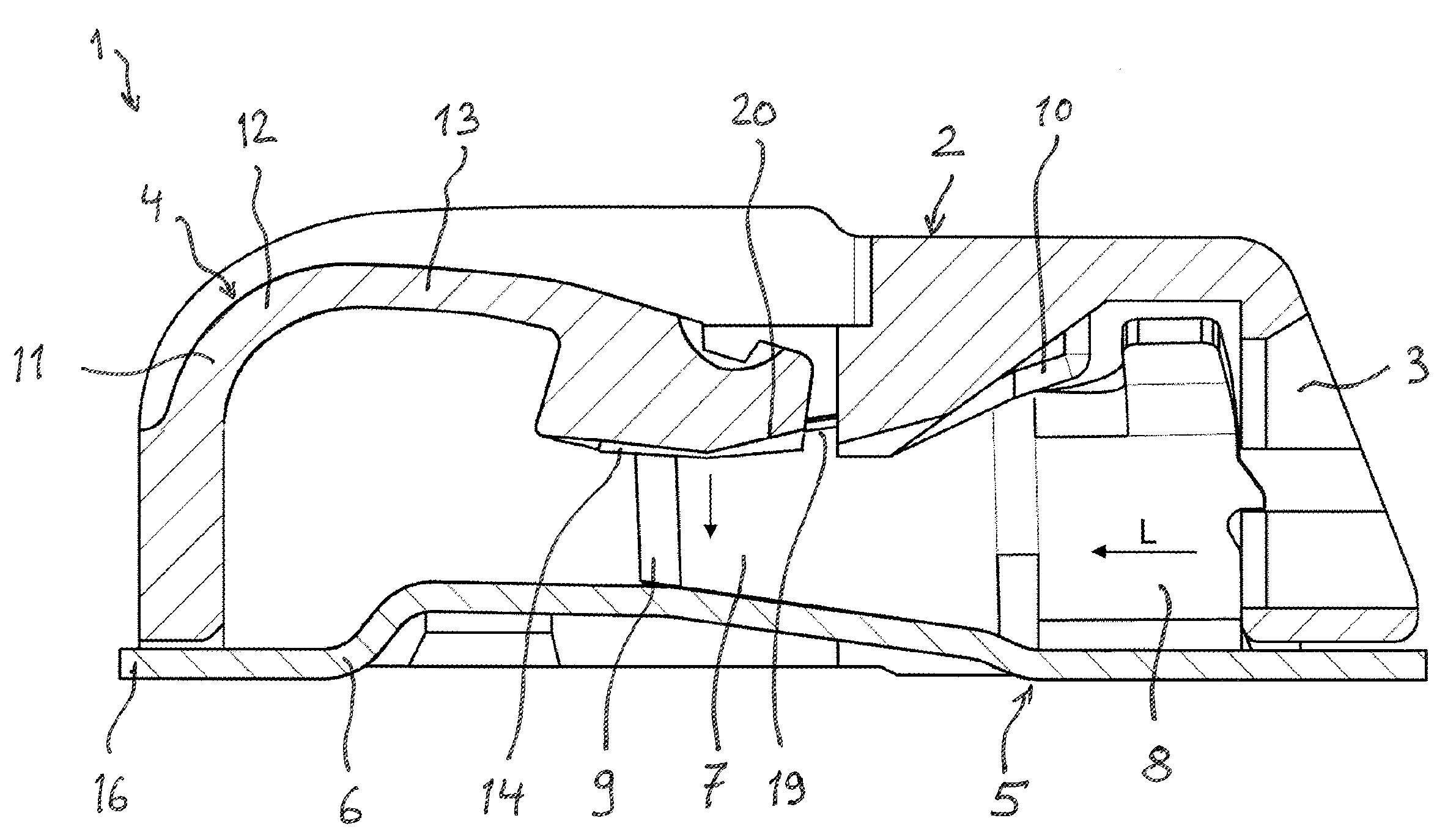
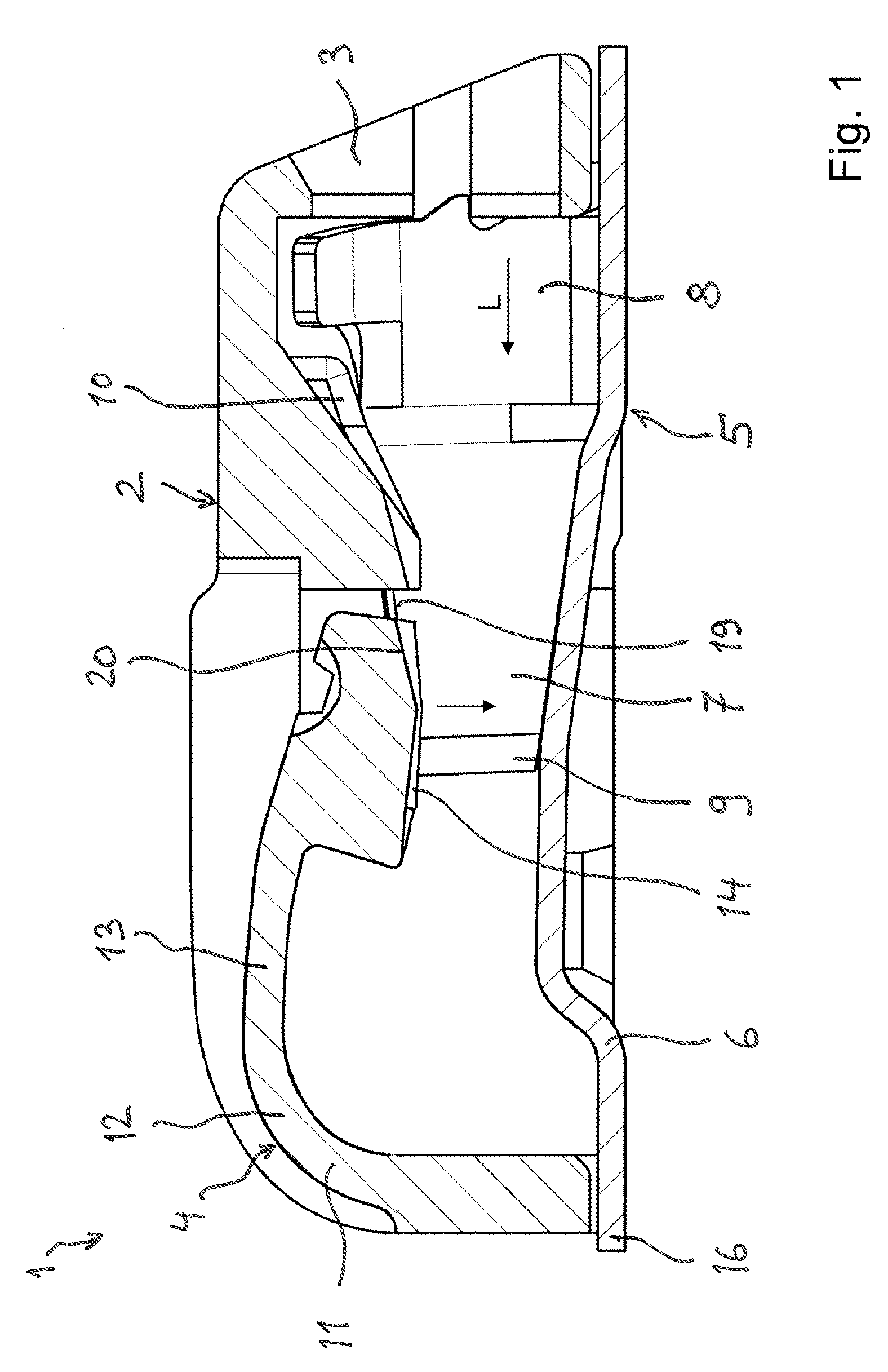
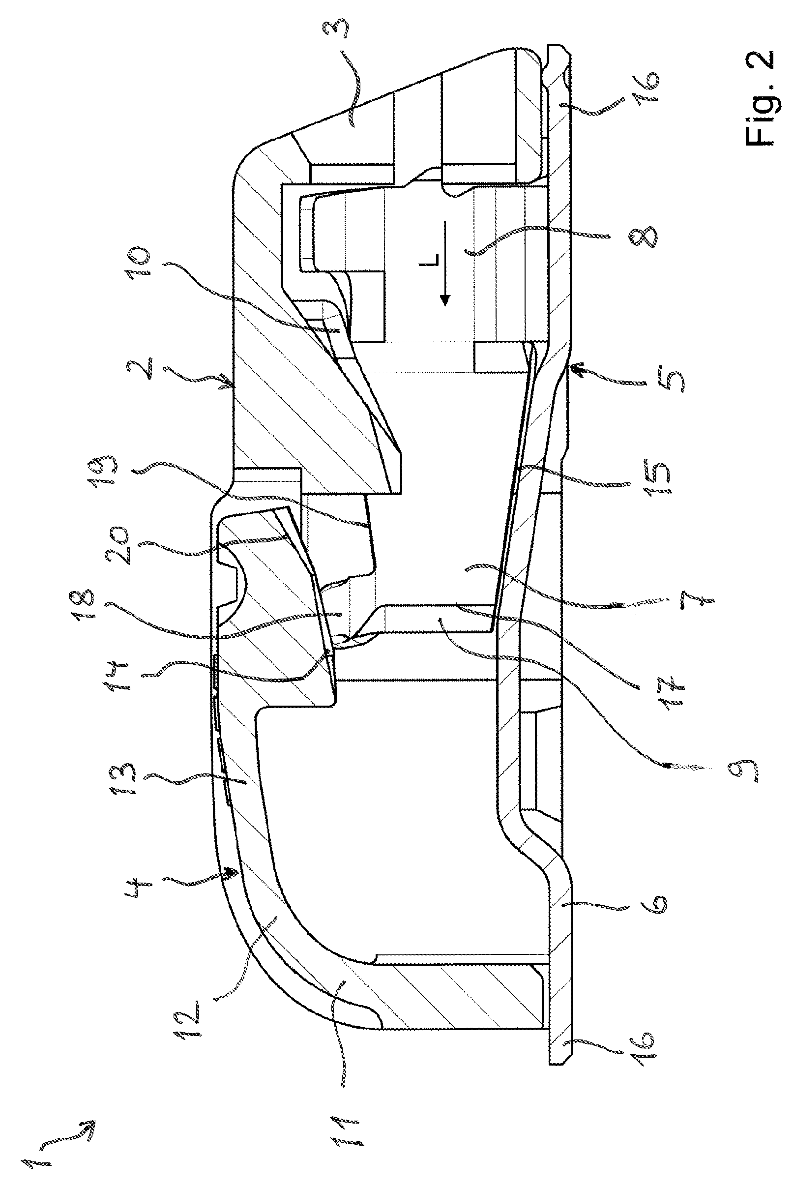
[0028]FIG. 1 shows a sectional view from the side of a conductor connection terminal 1. The conductor connection terminal 1 has an insulating housing 2 having a conductor insertion opening 3 in the front side and an actuating pushbutton 4 on the rear side, which is opposite the conductor insertion opening 3 in the insulating housing 2. A spring-force clamping connection 5 is installed in the insulating housing 2, and is formed as a contact frame with a base plate 6 and two spring tongues 7 which are transverse to the base plate 6 and are spaced apart from one another. The spring tongues 7 are integrally connected to the base plate 6 in a section which adjoins the conductor insertion opening 3 and forms a root region 8. For this purpose, the spring tongues 7 are formed integrally from a sheet-metal material with the base plate 6. The root region 8 is in this case curved in a direction transverse to the base plate 6 in order to form a conductor insertion funnel for inserting an electr...


PUM


Abstract

A conductor connection terminal (1) comprising an insulating housing (2) and comprising at least one spring-force clamping connection (5) in the insulating housing (2) for making the terminal connection of an electrical conductor is described. The spring-force clamping connection (5) has a base plate (6) and at least one spring tongue (7), which is at an angle to the base plate (6), is connected in a root region (8) to the base plate (6) and extends with its tongue end (9), which is movable in spring-elastic fashion, in a conductor plug-in direction (L). The free tongue end (9) is spaced apart from the base plate (6) by a gap (15). The insulating housing (2) has at least one actuating pushbutton (4), which interacts with the tongue end (9) opposite the base plate (6) and has an actuating section (14), which extends in the direction towards the base plate (6), for deflecting the spring tongue (7) transversely to the direction of extent of the spring tongue (7). The actuating pushbutton (4) has at least one resting section (20), which is designed in each case at an associated tongue end (9) to rest on a lateral peripheral edge (19) of the associated tongue end (9) and to shift the tongue end (9) in the direction of the base plate (6) whilst reducing the width of the gap (15) when the actuating pushbutton (4) is shifted in the direction of the base plate (6) so as to open a clamping connection formed by the spring tongue (7) for an electrical conductor of which a terminal connection is intended to be made.

Description

FIELD OF THE INVENTION[0001]The invention relates to a conductor connection terminal comprising an insulating housing and comprising at least one spring-force clamping connection in the insulating housing for making the terminal connection of an electrical conductor and wherein the spring-force clamping connection has a base plate and at least one spring tongue, which is at an angle to the base plate and is connected in a root region to the base plate and extends with its tongue end, which is movable in spring-elastic fashion, in a conductor plug-in direction, and wherein the free tongue end is spaced apart from the base plate by a gap, and the insulating housing has at least one actuating pushbutton, which interacts with the tongue end opposite the base plate and has an actuating section for deflecting the spring tongue transversely to the direction of extent of the spring tongue, which actuating section extends in the direction towards the base plate.BACKGROUND OF THE INVENTION[00...

Claims


Application Information

Patent Timeline
Patent Type & Authority Patents(United States)
IPC IPC(8): H01R13/10H01R33/00H01R4/48
CPCH01R4/48H01R4/4836H01R12/515H01R4/48365
Inventor GASSAUER, STEPHANWENIG, FABIAN
Owner WAGO VERW GMBH
Why Eureka
Try Eureka