Transiently mobile tibial engagement

a tibial bone and mobility technology, applied in the field of orthopaedic prostheses, to achieve the effect of preventing or minimizing the tibial bone component, and maximum tibial bone coverag

Active Publication Date: 2015-12-15
ZIMMER INC
View PDF24 Cites 8 Cited by
  • Summary
  • Abstract
  • Description
  • Claims
  • Application Information

AI Technical Summary

Benefits of technology

[0010]The present invention provides a tibial prosthesis having an articulating component and a tray component. The articulating component is configured for attachment to the tray component. Additionally, the articulating component may be attached to the tray component in a first condition in which the articulating component is at least rotatable relative to the tray component. This allows for the tray component to be attached to the tibia in a position that provides for proper rotation and / or alignment of the tray component with respect to the tibia to achieve maximum tibial bone coverage and / or to prevent or minimize the tray component from overhanging the resected tibia. Then, the articulating component may be rotated and / or translated to a position that provides for proper, anatomical alignment of the articulating component with a femoral prosthesis. Once in the desired position, a locking mechanism is used to rotationally and / or translationally fix the articulating component to the tray component. This allows the articulating component to be placed in a second condition in which the articulating component is rotationally and translationally fixed to the tray component to form a fixed bearing tibial prosthesis.
[0011]In order to implant the tibial prosthesis of the present invention, the tray component is implanted and secured to the resected proximal tibia of a patient in a position that maximizes coverage of the resected proximal tibia by the tray component and / or minimizes plate overhang of the resected proximal tibia. Then, the articulating component may be secured to the tray component in the first condition in which it is at least rotatable relative to the tray component. The surgeon may then trial the tibial prosthesis while the articulating component of the tibial prosthesis is allowed to rotate and / or translate into a position that provides for the most desirable articulation with the femur and / or femoral prosthesis, i.e., the articulating component self-aligns to optimize its position during joint articulation. Specifically, due to the ability of the articulating component of the tibial prosthesis to rotate and / or translation relative to the tray component, the articulating component will rotate and / or translate into a position in which it is properly aligned with the femoral prosthesis as the knee of the patient is flexed or otherwise manipulated during a trial reduction. Alternatively, the surgeon may manually set the articulating component in the desired rotational and / or translational orientation relative to the tray component. Once in this position, a locking mechanism is secured to the articulating component and / or tray component to place the articulating component in a second condition in which it is rotationally and / or translationally fixed to the tibial tray.
[0012]In one form thereof, the present invention provides a tibial prosthesis including a tray component having a superior surface; an articulating component moveably secured to the tray component, the articulating component at least one of translatable and rotatable relative to the tray component in a plane parallel to the superior surface of the tray component, the articulating component lockable in a plurality of differing positions, the plurality of differing positions differing from one another by at least one of translation and rotation; and a lock securable to at least one of the tray component and the articulating component to fix the rotational and translational position of the articulating component relative to the tray component in a number of different ones of the plurality of differing positions.

Problems solved by technology

However, implanting the tibial prosthesis at a position in which it is in the most desirable rotational position with respect to the femoral prosthesis may not result in the implantation of the tibial prosthesis in the most desirable rotational position with respect to the resected proximal tibia.

Method used


Image

  • Transiently mobile tibial engagement
  • Transiently mobile tibial engagement
  • Transiently mobile tibial engagement

Examples


Embodiment Construction

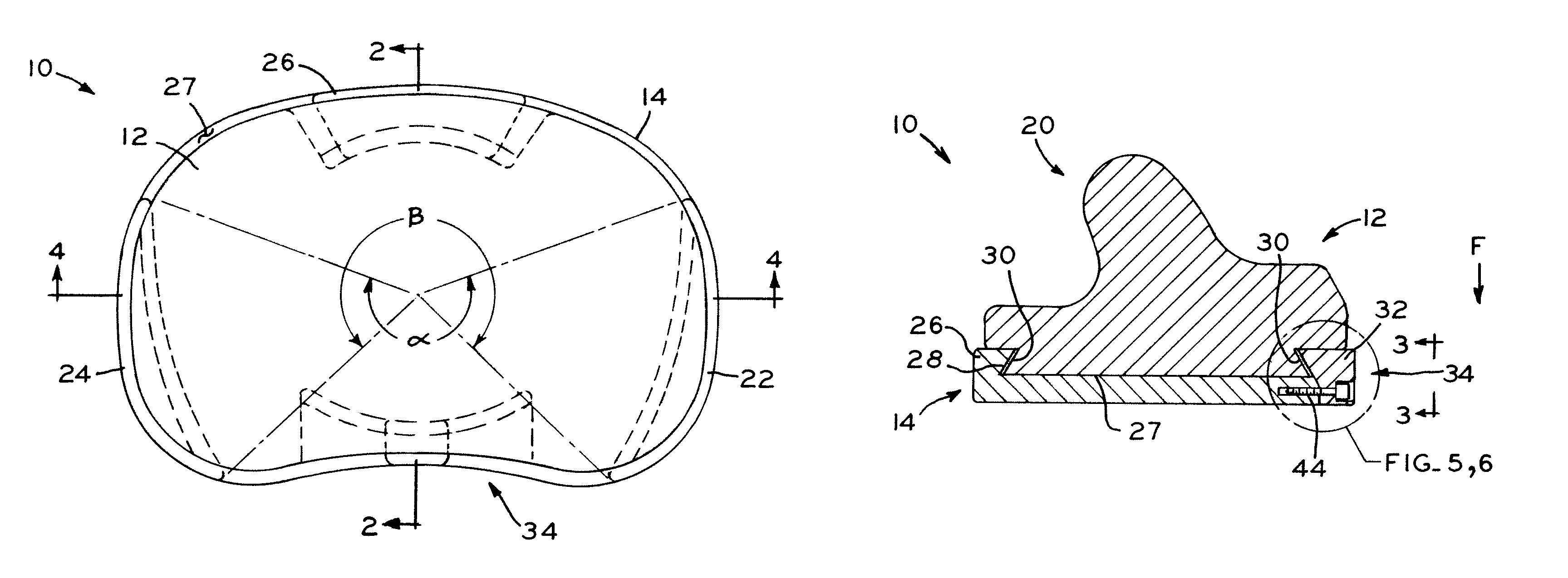
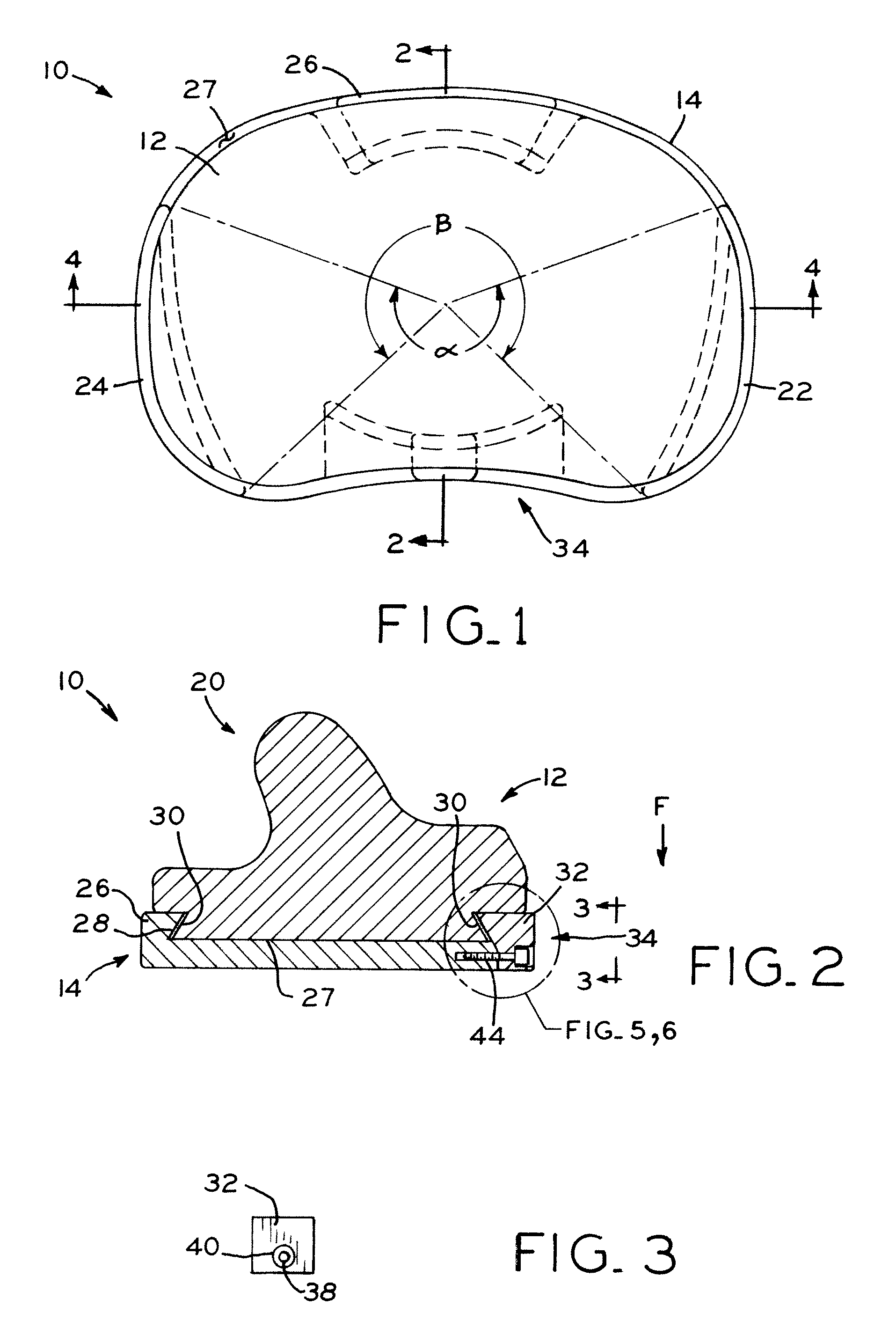
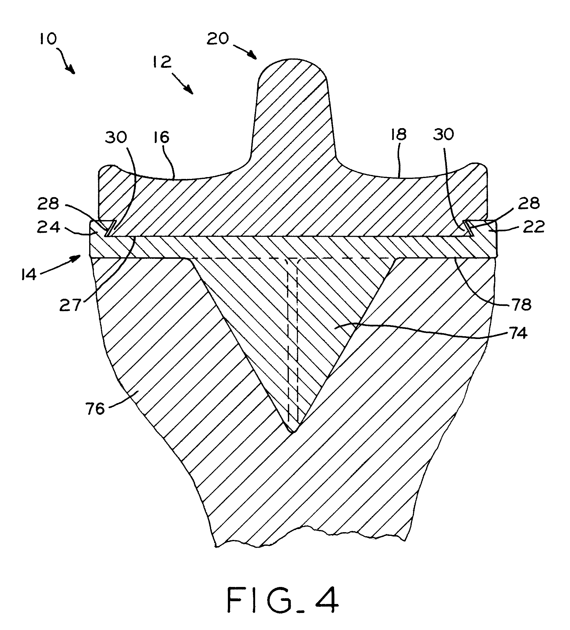
[0025]Referring to FIGS. 1, 2, and 4, tibial prosthesis 10 is shown in an assembled condition and includes articulating component 12 and tray component 14. While shown and described herein with specific reference to a right knee application, tibial prosthesis 10 may also be configured for use in a left knee application. Referring to FIG. 4, articulating component 12 includes a pair of opposing, concave articulating surfaces 16, 18 that are configured for articulation against opposing convex condyles of a femur or femoral prosthesis (not shown). Tibial eminence 20 extends upwardly between opposing articulating surfaces 16, 18. While shown and described herein as including tibial eminence 20, it is envisioned that tibial eminence 20 may also be absent.

[0026]Referring to FIGS. 2 and 4, rails 22, 24, 26 project upwardly from superior surface 27 of tray component 14 and define interior dovetail-shaped grooves 28 that interact with corresponding dovetail projections 30 on articulating com...


PUM


Abstract

The present invention relates to a tibial prosthesis having an articulating component and a tray component. The articulating component is configured for attachment to the tray component. Additionally, the articulating component may be attached to the tray component in a first condition in which the articulating component is at least rotatable relative to the tray component. This allows for the tray component to be attached to the tibia in a position that provides for proper rotation of the tray component with respect to the tibia and / or prevents the tray component from overhanging the resected tibia. Then, the articulating component may be rotated and / or translated to a position that provides for proper alignment of the articulating component with a femoral prosthesis. Once in this positioned, a locking mechanism is used to rotationally fix the articulating component to the tray component.

Description

CROSS-REFERENCE TO RELATED APPLICATIONS[0001]This application claims the benefit under Title 35 U.S.C. §119(e) of U.S. Provisional Patent Application Ser. No. 61 / 114,698, entitled TRANSIENTLY MOBILE TIBIAL ENGAGEMENT, filed on Nov. 14, 2008, the disclosure of which is expressly incorporated by reference herein.BACKGROUND[0002]1. Field of the Invention[0003]The present invention relates to orthopedic prostheses and, particularly, to tibial prostheses.[0004]2. Description of the Related Art[0005]Orthopedic prostheses are commonly utilized to repair and / or replace damaged bone and tissue in the human body. For example, a knee prosthesis may be implanted during a total knee arthroplasty to replace damaged or destroyed bone in the tibia and / or femur and to recreate the natural, anatomical articulation of the knee joint. A femoral prosthesis may be shaped to replicate one or both of the natural femoral condyles. After resecting the distal end of the femur, one side of the femoral prosthes...

Claims


Application Information

Patent Timeline
Patent Type & Authority Patents(United States)
IPC IPC(8): A61F2/38A61F2/30
CPCA61F2/3868A61F2/389A61F2002/30387A61F2220/0025
Inventor EARL, BRIAN D.SANFORD, ADAM H.
Owner ZIMMER INC
Why Eureka
Try Eureka