Golf club head with adjustable center of gravity

a golf club and center of gravity technology, applied in the field of golf club heads, can solve the problems of not optimizing weight adjustment, achieve the effect of maximizing aesthetic appearance, facilitating movement and fixing weights, and preserving the function of movable weights

Active Publication Date: 2015-12-15
TOPGOLF CALLAWAY BRANDS CORP
View PDF32 Cites 101 Cited by
  • Summary
  • Abstract
  • Description
  • Claims
  • Application Information

AI Technical Summary

Benefits of technology

[0007]The present invention is a novel way of working with adjustable products. The present invention allows consumers to easily move and fix a weight at any location within one or more channels disposed in the golf club head in such a way to maximize aesthetic appearances while preserving the function of the movable weight. The objective of this invention is to provide an adjustable weight with minimal or no effect on appearance at address while maximizing the ability of the weight to adjust center of gravity height. Additional goals include minimizing the fixed component of the structure dedicated to the weighting system and also minimizing any potential effect on impact sound. Yet another object of the present invention is an adjustable weighting feature for lateral or vertical center of gravity control which is placed to maximize effectiveness and may be entirely concealed from view at address.

Problems solved by technology

The prior art includes several different solutions for adjustable weighting, but these solutions do not optimize weight adjustment.

Method used


Image

  • Golf club head with adjustable center of gravity
  • Golf club head with adjustable center of gravity
  • Golf club head with adjustable center of gravity

Examples


first embodiment

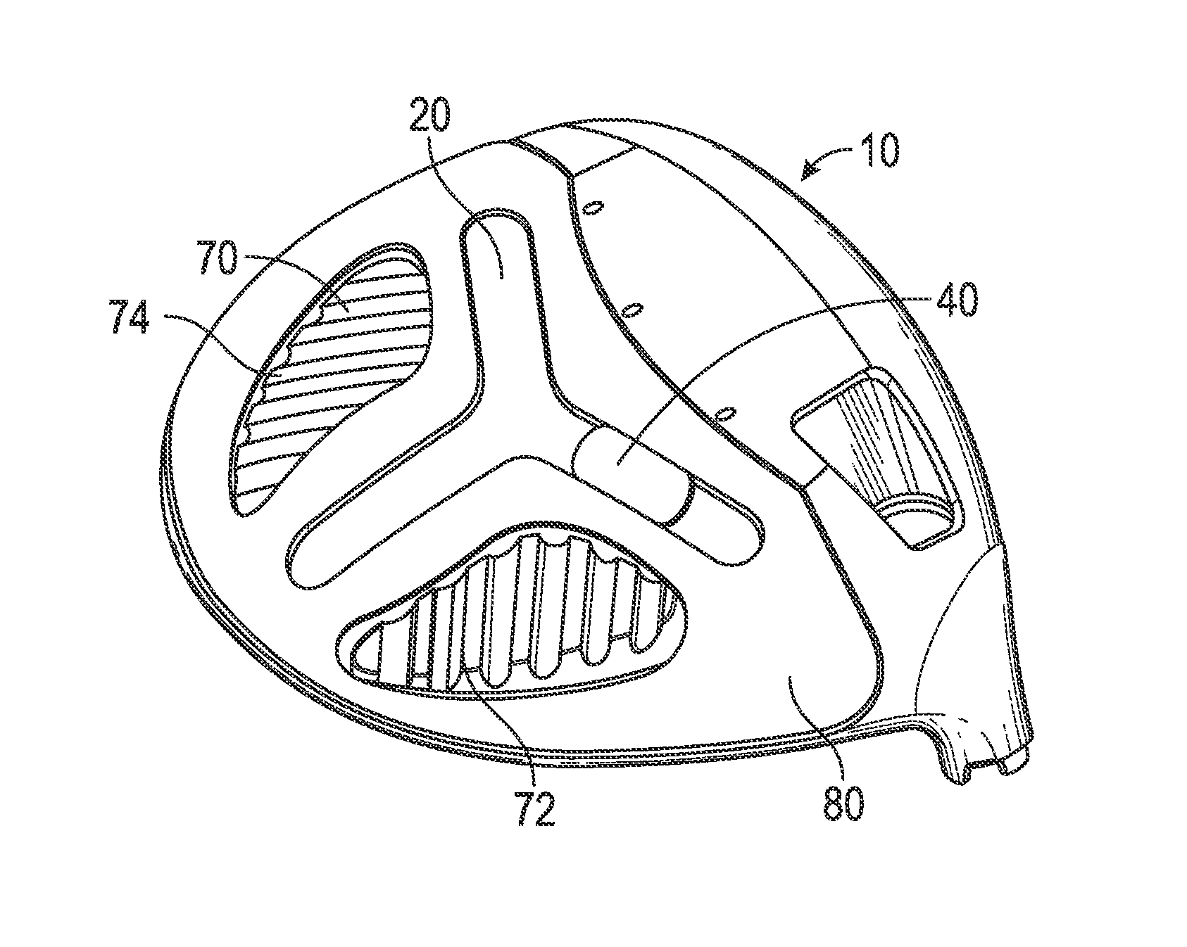
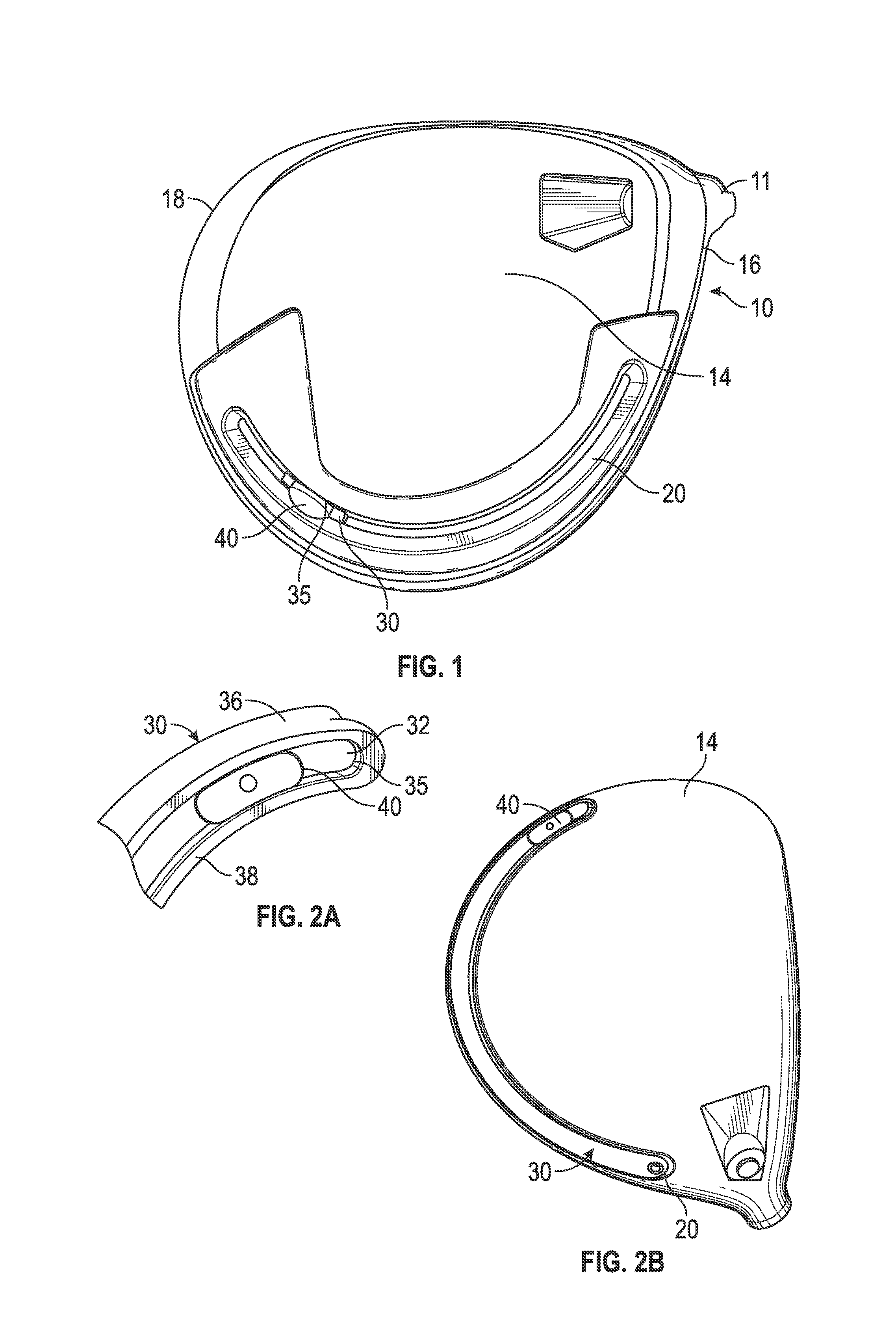
[0044]the present invention is shown in FIG. 1. The golf club head 10 comprises a channel 20 disposed within the sole 14 of the golf club head, though in alternative embodiments the channel 20 may be disposed in a ribbon or skirt portion or in the crown 12 of the golf club head 10. The channel 20 extends from a heel side 16 of the club head proximate a hosel 11 to a toe side 18 of the golf club head 10 along the rear edge of the sole 14, and has a curved cross-sectional shape with an internal width W1 that is greater than an external opening width W2. A slidable cartridge 30 that is significantly smaller in length than the channel 20 is disposed within the channel 20, and is inserted into the channel 20 during construction of the golf club head so that it is permanently retained within the channel 20. The cartridge 30 includes an upper slot or opening 35 sized to receive a weight insert 40, which is customizable by a user. The weight insert 40 may be affixed to the cartridge 30 with...

third embodiment

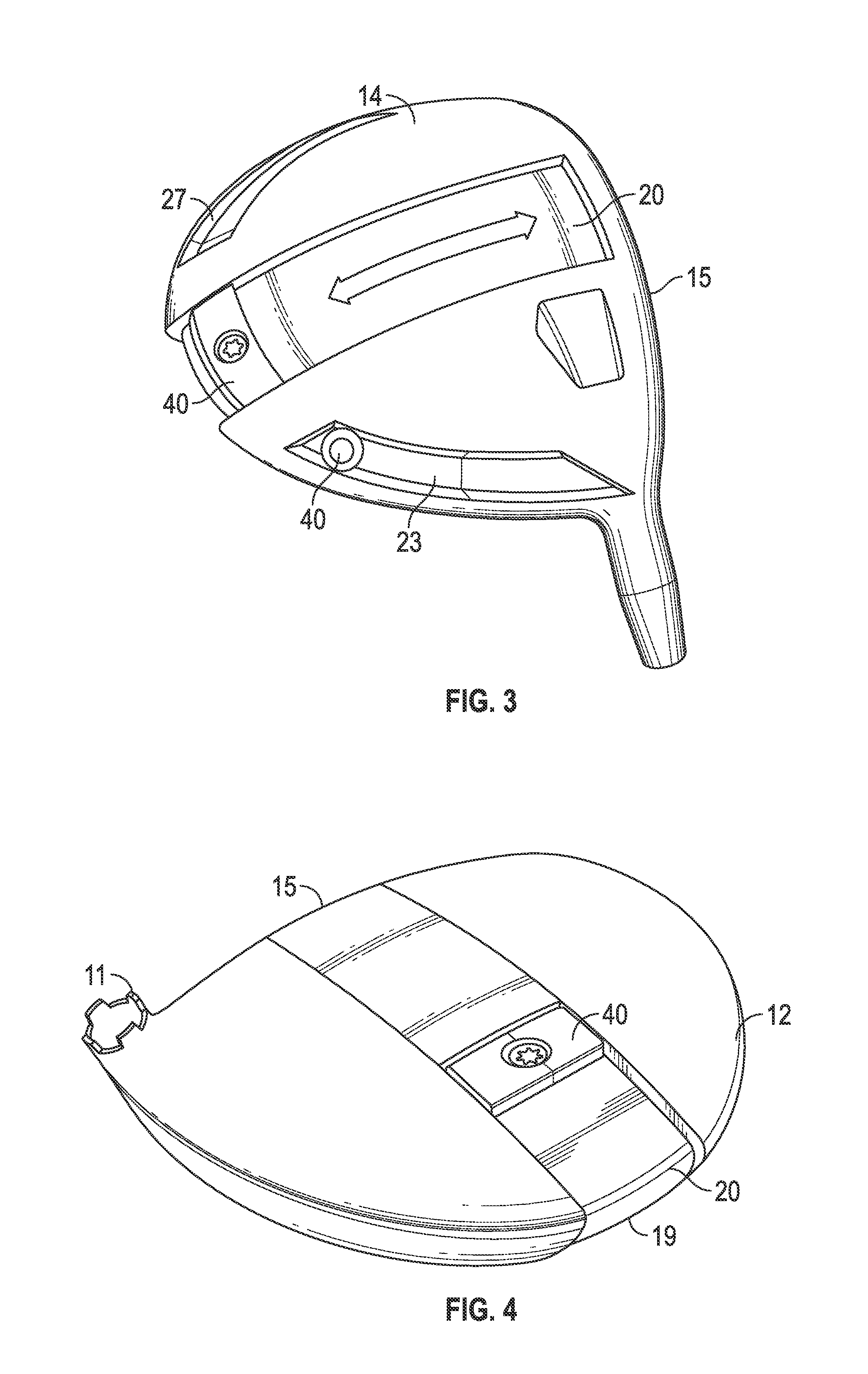
[0046]the present invention is shown in FIGS. 3-4. This embodiment is similar to the embodiment shown in FIGS. 28-29 of U.S. patent application Ser. No. 14 / 033,218, the disclosure of which is hereby incorporated by reference in its entirety herein, in that the slidable weight 40 is adjustable in a direction perpendicular to the face 15 of the golf club head 10, but in this embodiment the channel 20 extends from the sole 14 onto the crown 12 via the rear side 16 of the golf club head 10, thus permitting the slidable weight 40 to be moved from the sole 14 to the crown 12 and vice versa. This configuration allows a user to create high / low and forward / rearward center of gravity locations for the golf club head 10. This embodiment also incorporates two secondary channels 25, 27 that extend along the rear side 16 of the golf club head 10 on opposite sides of the central channel 20 so that secondary slidable weights 40 can be used to create draw and fade bias on the heel 16 and toe 18 side...


PUM


Abstract

A golf club head comprising multiple means of adjusting the location of the center of gravity, and the bias, is disclosed herein. In a preferred embodiment, the golf club head comprises a non-metal medallion comprising a channel that is affixed to one of the crown and the sole, a slidable weight sized to fit within the channel, and a cover that attaches to the medallion and locks the slidable weight within the channel at a location selected by a user. The cover preferably includes at least one cutout so that the slidable weight is at least partially visible to the user when it is locked within the channel. The cover also includes additional cutouts that receive protrusions extending from the medallion to more securely attach the cover to the medallion.

Description

CROSS REFERENCES TO RELATED APPLICATIONS[0001]The present application claims priority to U.S. Provisional Patent Application No. 61 / 893,728, filed on Oct. 21, 2013, and is a continuation-in-part of U.S. patent application Ser. No. 14 / 033,218, filed on Sep. 20, 2013, which is a continuation-in-part of U.S. patent application Ser. No. 13 / 923,571, filed on Jun. 21, 2013, which is a continuation-in-part of U.S. patent application Ser. No. 13 / 778,958, filed on Feb. 27, 2013, which claims priority to U.S. Provisional Patent Application No. 61 / 727,608, filed on Nov. 16, 2012, the disclosure of each of which is hereby incorporated by reference in its entirety herein. The present application also is a continuation-in-part of U.S. patent application Ser. No. 13 / 766,658, filed on Feb. 13, 2013, which claims priority to U.S. Provisional Patent Application No. 61 / 746,348, filed on Dec. 27, 2012, the disclosure of each of which is hereby incorporated by reference in its entirety herein.STATEMENT ...

Claims


Application Information

Patent Timeline
Patent Type & Authority Patents(United States)
IPC IPC(8): A63B53/04A63B53/06A63B59/00
CPCA63B53/06A63B53/0466A63B59/0074A63B2053/0491A63B60/52A63B60/04A63B53/0437A63B53/0433A63B53/045A63B2053/0495
Inventor FOSTER, PHILIP G.MYERS, MATTHEWKIM, WEE JOUNGSUTTON, STEVEN C.TANG, LARRYHOLT, DENVER
Owner TOPGOLF CALLAWAY BRANDS CORP
Why Eureka
Try Eureka