Passive range estimating engagement system and method

a passive range estimation and engagement system technology, applied in the direction of direction/deviation determining electromagnetic systems, instruments, and using reradiation, can solve the problems of degraded correlation performance, diminished resolvability, and degraded correlation performance, and achieve the effect of improving system performan

Active Publication Date: 2015-12-15
LOCKHEED MARTIN CORP
View PDF29 Cites 20 Cited by
  • Summary
  • Abstract
  • Description
  • Claims
  • Application Information

AI Technical Summary

Benefits of technology

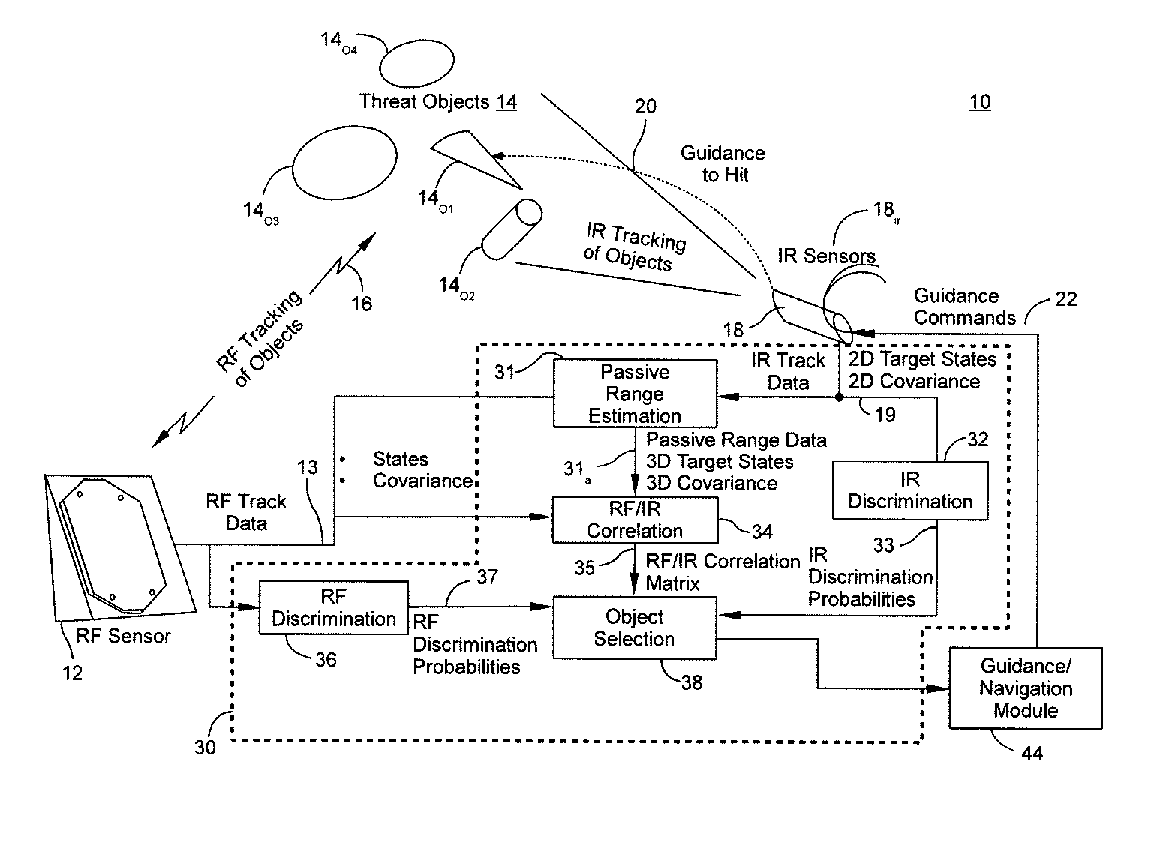
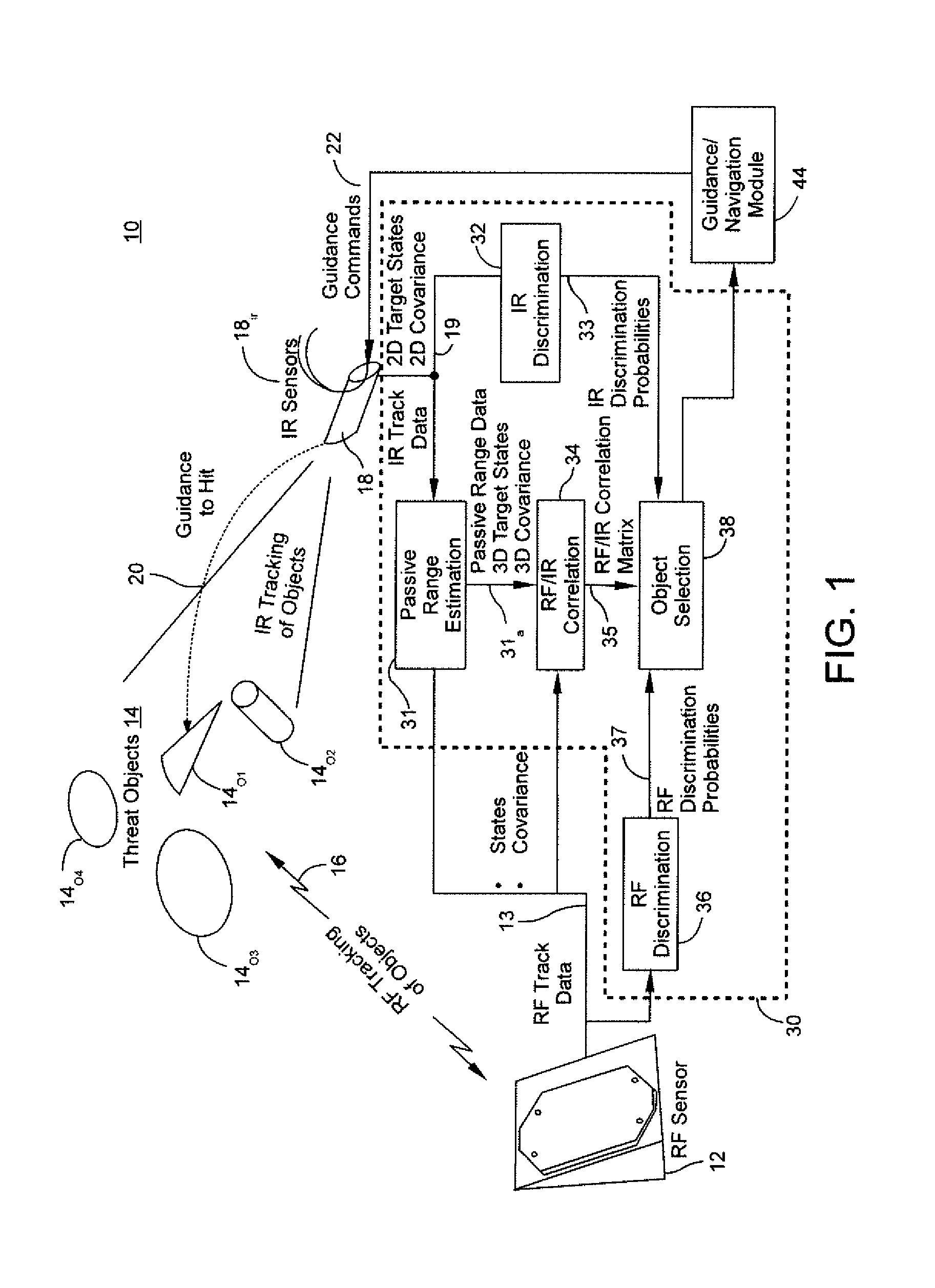
[0007]An aspect of the present disclosure derives a 3-dimensional target position and velocity using 2-dimensional IR sensor angular measurements for objects travelling in a ballistic manner within the IR sensor's FOV. In one embodiment, the resulting 3-dimensional states are used to generate updated inputs for correlation and object selection, which may yield enhanced system performance. The selection of the target object is used to drive missile guidance algorithms and complete the intercept.

Problems solved by technology

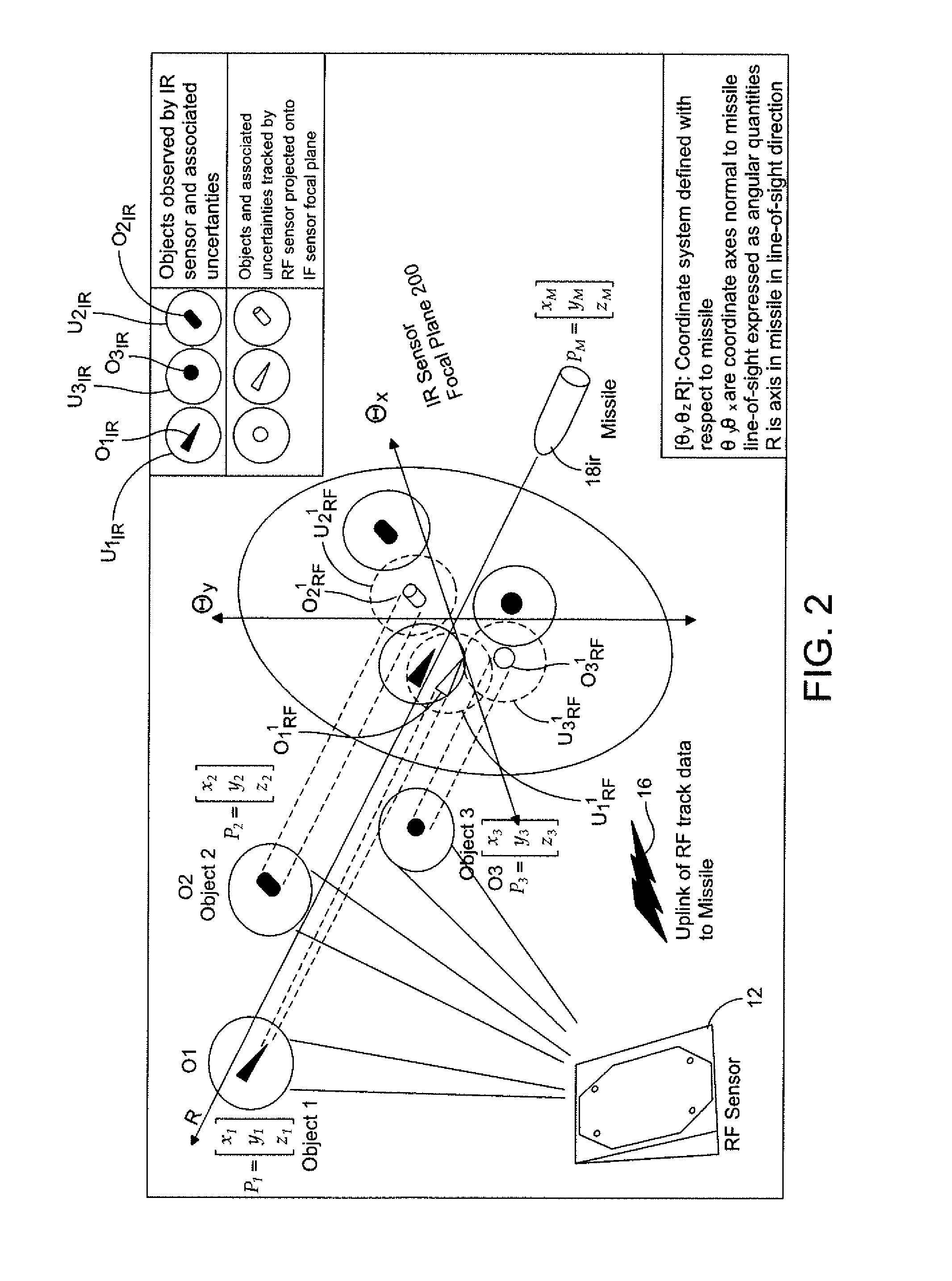
However, uncertainties in both the RF and IR tracks, due at least in part to measurement noise and systematic errors can lead to degraded correlation performance.
Objects closely spaced within the IR sensor FOV relative to the magnitude of their uncertainties results in diminished resolvability.
This brings about degraded correlation performance.
Cases where the object of interest is incorrectly determined may result in extremely degraded intercept performance.
However, due to the “angles-only” nature of the IR sensor measurements, missile-to-object range is not directly available.
Prior art implementations of BM engagement systems rely on object separation within the IR sensor FOV to be above an identified threshold and do not account for missile-to-object range in their correlation processing.
For cases with objects spaced closely in angle with respect to the IR sensor focal plane, complications may result.

Method used


Image

  • Passive range estimating engagement system and method
  • Passive range estimating engagement system and method
  • Passive range estimating engagement system and method

Examples


Embodiment Construction

[0017]It is to be understood that the figures and descriptions of the present invention have been simplified to illustrate elements that are relevant for a clear understanding of the present invention, while eliminating, for purposes of clarity, many other elements found in radar detection, tracking and engagement systems that employ RF and IR sensors. However, because such elements are well known in the art, and because they do not facilitate a better understanding of the present invention, a discussion of such elements is not provided herein. The disclosure herein is directed to all such variations and modifications known to those skilled in the art.

[0018]In the following detailed description, reference is made to the accompanying drawings that show, by way of illustration, specific embodiments in which the invention may be practiced. It is to be understood that the various embodiments of the invention, although different, are not necessarily mutually exclusive. Furthermore, a par...


PUM


Abstract

A system and method for determining a 3-dimensional target position and velocity using 2-dimensional IR sensor angular measurements for objects travelling in a ballistic manner within an IR sensor's field of view (FOV). Resulting 3-dimensional states may be used to generate updated inputs for correlation and object selection to drive missile guidance and intercept operations.

Description

FIELD OF THE INVENTION[0001]The disclosed system and method relate to missile tracking. More specifically, the disclosed system and method relate to tracking and intercept of a ballistic missile (BM).BACKGROUND OF THE INVENTION[0002]In the engagement and intercept of a hostile ballistic missile (BM), a weapon system will typically track the ballistic missile objects using a ground-based radio frequency (RF) sensor and transmit track information to an intercepting missile for processing. The intercepting missile is typically equipped with an infrared (IR) sensor which is used to acquire and track the hostile ballistic missile objects as part of the engagement sequence.[0003]Hostile ballistic missiles, however, can be expected to deploy decoy objects to conceal the warhead(s) and avoid tracking and interception. Multiple objects from one or more BM launch events may therefore be present in the IR sensor field of view (FOV). In order to select and guide to the targeted object, a correl...

Claims


Application Information

Patent Timeline
Patent Type & Authority Patents(United States)
IPC IPC(8): G01S13/86F41G7/00G01S7/292G01S5/02G01S13/66G01S13/72F41H11/02G01S13/88G01S7/295
CPCF41G7/008F41H11/02G01S13/726G01S13/86G01S13/883G01S7/292G01S5/0294G01S13/72G01S7/295G01S7/2923G01S13/66F41G7/2206F41G7/2253F41G7/2293G01S3/783
Inventor BOARDMAN, JONATHAN A.BOKA, JEFFREY B.MOOKERJEE, PURUSOTTAMPATEL, NARESH R.
Owner LOCKHEED MARTIN CORP
Why Eureka
Try Eureka