Vacuum collector assembly for lawn tractors

a vacuum collector and lawn tractor technology, applied in the field of vacuum collector assembly, can solve the problems of ineffective compromise the handling and operation etc., and achieve the effects of convenient storage, convenient release of the lawn tractor, and convenient attachment to the lawn tractor

Active Publication Date: 2015-12-22
RONNING NORMAN EDWARD +1
View PDF25 Cites 6 Cited by
  • Summary
  • Abstract
  • Description
  • Claims
  • Application Information

AI Technical Summary

Benefits of technology

[0007]It is an object of the present invention to provide a vacuum collector assembly that is forwardly mounted more toward the lawn tractor's motor to re-establish an overall center of gravity that is conducive to maintaining stable and safe operation of the lawn tractor, even in instances of managing short-radius turns and engaging in ascending and descending operational runs.
[0008]It is an object of the present invention to provide a vacuum collector assembly that reduces the effective length of piping extending from the lawn tractor's chute to a vacuum chamber and required number of pipe bends to yield enhanced net air flows, an appreciable reduction of clogging and blocking of the piping for more efficient and comprehensive collection of grass clippings and other releasable debris, such as leafs, twigs and small branches, from the lawn surface, and greater operating efficiency of the vacuum motor, notably in terms of less fuel consumption and longer operational life.
[0010]It is another object of the present invention to provide a vacuum collector assembly that allows an individual operator to readily attach to the lawn tractor for operation and easily release it apart therefrom to allow for convenient storage.
[0011]It is another object of the present invention to provide a vacuum collector attachment that is fabricated from high-strength materials to offer prolong and reliable operation.
[0012]It is yet another object of the present invention to provide a vacuum collector assembly that yields cost savings to its owner and / or operator in terms of less downtime for repairs and maintenance of the lawn tractor and less fuel consumption for both the lawn tractor and operable components of the vacuum collector assembly.
[0013]It is yet another object of the present invention to provide a vacuum collector assembly which accomplishes the foregoing and other objects and advantages and which is economical, durable, and fully effective in performing its intended functions without unduly compromising the stock performance and operation of the lawn tractor.

Problems solved by technology

Although this particular model as well as many of the towable vacuum attachments offered in art may adequately serve to collect and contain grass clipping and the like from the lawn surface, each is generally noted to compromise the handling and operation of the lawn tractor due to an appreciable increase in length arising from its attachment.
Additionally, as each of the collector bins becomes filled to capacity, the center of gravity of the lawn tractor and vacuum collector attachment is re-established more rearwardly behind the lawn tractor, thus undesirably contributing to ineffective handling and operation of the lawn tractor, particularly as one manages short-radius turns and / or engages in ascending and descending operational runs.
Consequently, the pipe's resultant operational length and its bending configuration contribute to periodic clogging of the pipe and / or buildup at one or more pipe bends, thus necessitating disassembly and re-assembly of the pipe's connections for cleaning so that one can restore the free or unrestricted flow of debris within the pipe and ultimately regain proper, efficient operation of the lawn tractor.

Method used


Image

  • Vacuum collector assembly for lawn tractors
  • Vacuum collector assembly for lawn tractors
  • Vacuum collector assembly for lawn tractors

Examples


Embodiment Construction

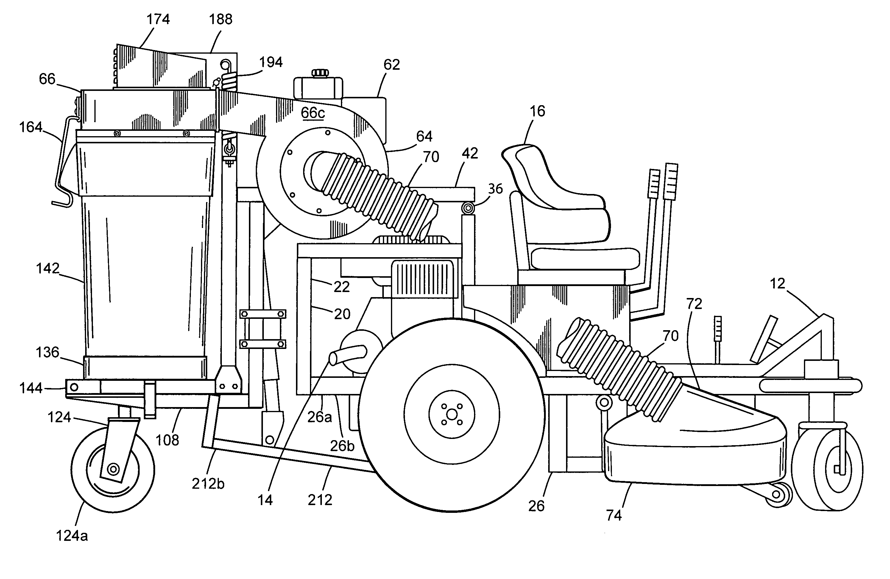
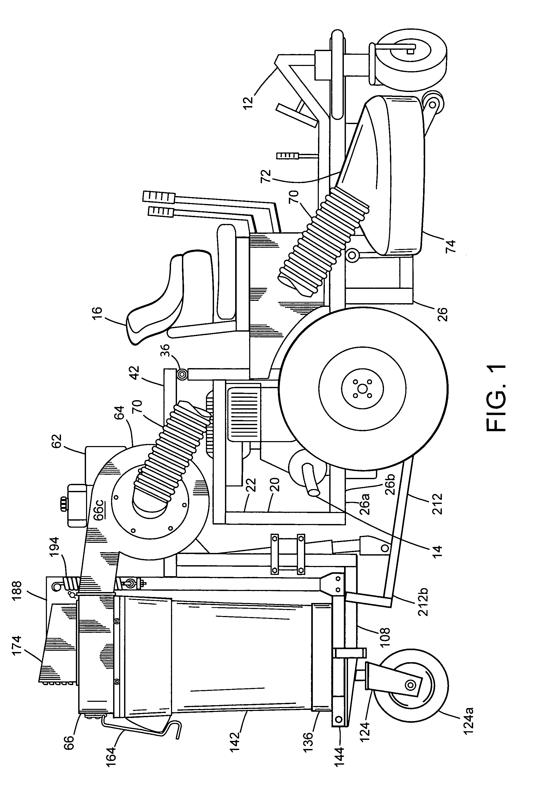
[0033]While this invention is susceptible of being embodied in many different forms, the preferred embodiment of the invention is illustrated in the accompanying drawings and described in detail hereinafter with the understanding that the present disclosure purposefully exemplifies the principles of the present invention and is not intended to limit the invention to the embodiments illustrated and presented herein. The present invention comprises utilitarian features for effectively and efficiently removing and collecting grass clippings and related debris from a lawn surface and other natural growth areas for later disposal, while retaining stability of the lawn tractor during operational runs.

[0034]Referring now to FIG. 1, there is shown generally at 10 vacuum collector assembly attached to a self-propelled lawn tractor 12 of the type generally known in the art to comprise a rear-mounted engine 14 and structural seating provisions 16 for allowing an individual operator to ride ato...


PUM


Abstract

A vacuum collector assembly comprises a mountable hitch having support posts connected to one another by horizontal supports and a hinge mechanism for connecting to a trailing carriage. The trailing carriage includes a lift assembly and an engine support frame for mounting thereon an engine operating conjunctively with an impeller assembly for developing negative pressure within a blower housing that is connected in between a receptacle hood and a lawn cutting deck. The engine support frame generally extends outwardly from a pair of vertical columns each having ends connected to support runners for situating atop thereof a pair of receptacles holders suited for receiving receptacle bins utilized in storing collected debris. The lift assembly comprises side arms functioning with a trailer jack having internal gearing made operable by an extension rod and handle assembly to facilitate rotation thereof that effects lifting and lowering of the trailing carriage apart and away from the mountable hitch to allow for wheeled transport and storage of the vacuum collector assembly.

Description

CROSS-REFERENCE TO RELATED APPLICATIONS[0001]This application claims the benefit of U.S. provisional patent application No. 61 / 630,263, filed Dec. 7, 2011, entitled “Vacuum Collector Assembly for Lawn Tractors,” the disclosures of which, including all attached documents, are incorporated herein by reference in their entirety for all purposesFIELD OF THE INVENTION[0002]The present invention relates in general to a vacuum collector assembly for utilization with a powered lawn tractor specifically equipped to mow and trim a lawn surface comprising a variety of grasses, weeds and other natural growths. In particular, the vacuum collector assembly, when used in conjunction with the lawn tractor, establishes an overall center of gravity that is conducive to maintaining stable operation of the lawn tractor which in turn contributes to efficient and comprehensive collection of grass and weed clippings and other loose debris, such as leafs, twigs and small branches, from the lawn surface.BAC...

Claims


Application Information

Patent Timeline
Patent Type & Authority Patents(United States)
IPC IPC(8): A01D43/06A01D43/077
CPCA01D43/077
Inventor RONNING, NORMAN EDWARDRONNING, PAUL NELS
Owner RONNING NORMAN EDWARD
Why Eureka
Try Eureka