
Self-service terminal

a terminal and self-service technology, applied in the field of self-service terminals, can solve the problems of limiting the way in which users outside the network management centre can interface, often affecting the user experience, etc., to achieve small and/or light and/or less expensive and/or affordable solutions

Active Publication Date: 2015-12-22
NCR CORP
View PDF13 Cites 13 Cited by
  • Summary
  • Abstract
  • Description
  • Claims
  • Application Information

AI Technical Summary

Benefits of technology

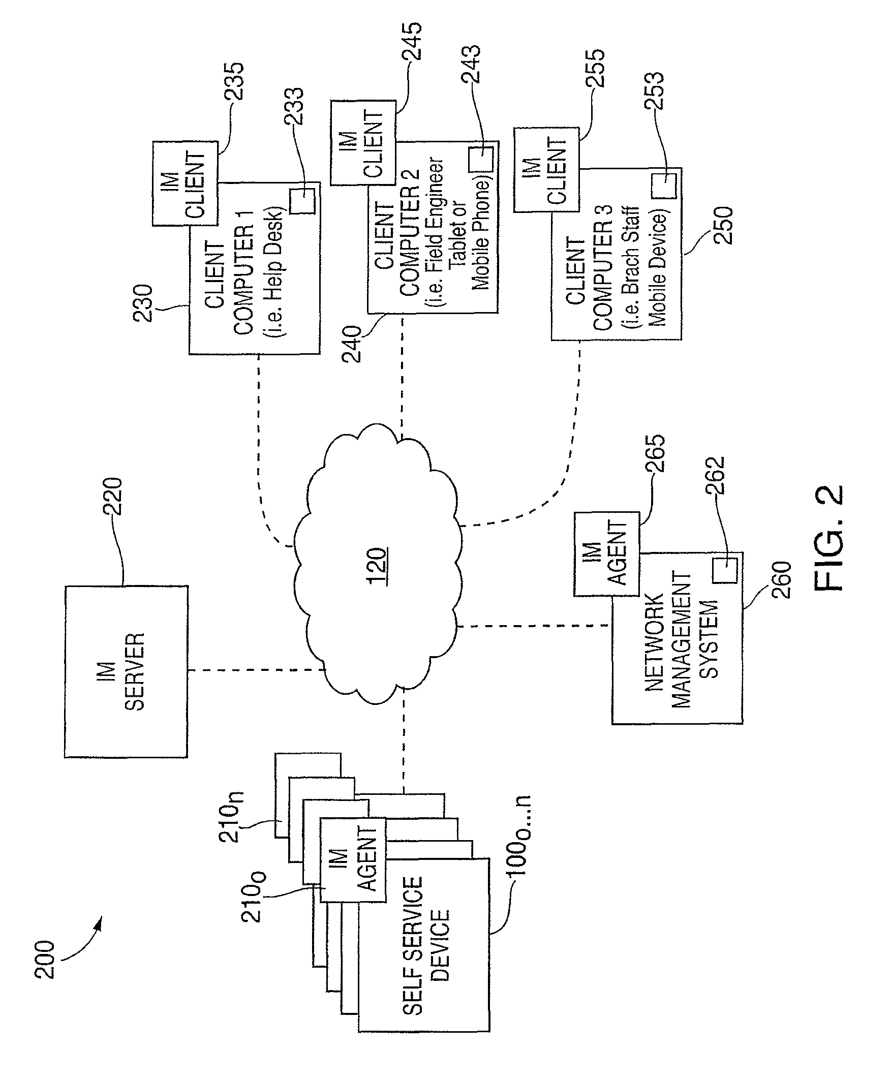
[0008]It is an aim of certain embodiments of the present invention to provide a central help desk terminal with instant presence information identifying when one or more terminals in a network are operational and to provide a user based locally or remotely with an efficient and straightforward way to monitor malfunction and attempt to correct the malfunction.
[0009]It is an aim of certain embodiments of the present invention to enable a network such as a financial network which includes a monitoring function to be continually updated with real time messages so that malfunction or other network statistic information can be continually updated and reacted to in a prompt and efficient manner.
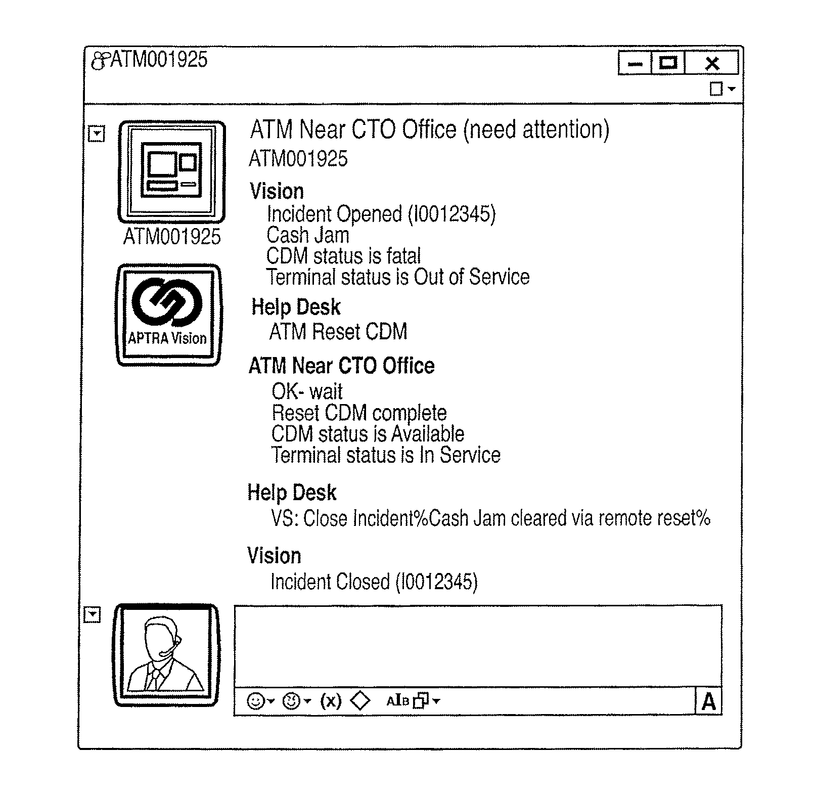
[0029]It should now be appreciates that embodiments according to this aspect have the advantage that instant messages can be utilized to identify the status of an Automated Teller Machine (ATM) (or other SST) and can issue commands to try to correct any malfunction that is detected in real-time.
[0039]Certain embodiments of the present invention provide a smaller and / or light and / or less expensive and / or more flexible system for network management than conventional systems.
[0040]Certain embodiments of the present invention provide a network management tool that can complement existing systems and which can provide an affordable solution to the management of networks.
[0042]Certain embodiments of the present invention provide a mechanism whereby operation of multiple terminals can be monitored in real time. Attempts can be made to correct any detected malfunction in a prompt fashion, and if such attempts fail, local service personnel or field engineers can be dispatched to correct the error in a prompt and observable manner.

Problems solved by technology

Management of such networks is often a complex and costly issue for those concerned with such matters.
Even in circumstances where such costly and complex management systems exist, action can be delayed due to constraints imposed upon the overall network by the system.
Conventional systems often limit the way in which users outside of the network management centre can interface with the SSTs to collect status information and attempt to correct malfunctions.

Method used


Image

  • Self-service terminal
  • Self-service terminal
  • Self-service terminal

Examples


Embodiment Construction

[0050]In the drawings like reference numerals refer to like parts.

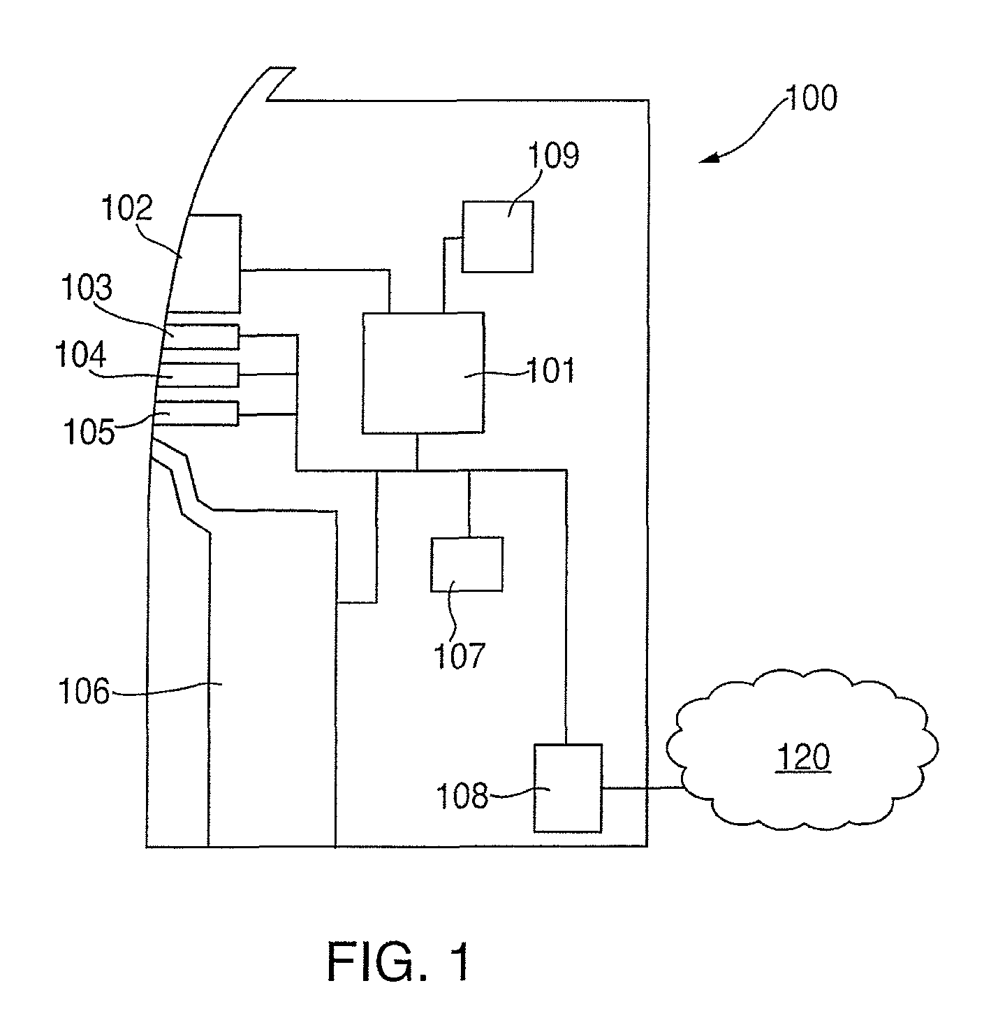
[0051]FIG. 1 illustrates a block diagram of a Self-Service Terminal (SST) 100 in the form of an Automated Teller Machine (ATM) according to an embodiment of the present invention. It will be understood that certain embodiments of the present invention are applicable to many different types of terminal such as ATMs, vending machines, Teller Cash Recyclers (TCRs), change machines, kiosks, Fast Lane POS and the like. Typically, in an ATM a sheet like item of media is to be moved from one location to another. Likewise, items of media such as, but not limited to, currency notes, checks, tickets, giros and the like may be deposited at and / or dispensed from such terminals.

[0052]The ATM 100 includes different modules for enabling transactions to be executed and recorded by the ATM 100. These ATM modules include customer transaction modules and service personnel modules. The ATM modules include an ATM controller 101, a custome...


PUM


Abstract

A method and apparatus are disclosed for determining a status of a Self-Service Terminal (SST) in a financial network. The method includes the steps of, from an SST comprising a node of a financial network, providing an instant message identifying a status of the terminal to a help desk terminal comprising a further node of the financial network.

Description

FIELD OF THE INVENTION[0001]The present invention relates to a method and apparatus for monitoring and controlling a Self-Service Terminal (SST). In particular, but not exclusively, the present invention relates to monitoring and controlling the operational status of an SST, such as an Automated Teller Machine (ATM).[0002]Many networks are known in which multiple Self-Service Terminals (SSTs) are connected together for use by members of the public or members of an organization.[0003]For example, many SSTs in the form of Automated Teller Machines (ATMs) are networked together as part of a financial network. The ATMs which form nodes or network end points may be located in bank branches, in building lobbies or other sites spread out over a city or country.[0004]Management of such networks is often a complex and costly issue for those concerned with such matters. Typically, dedicated systems are required to collect data such as status information and / or level of consumables or the like...

Claims


Application Information

Patent Timeline
Patent Type & Authority Patents(United States)
IPC IPC(8): G06F15/16G07F19/00H04L12/26H04L29/06H04L12/24G06Q20/18H04L12/58
CPCH04L43/00G06Q20/18G07F19/209H04L43/0817H04L65/1006H04L65/1093H04L41/026H04L51/046G06Q20/386G07F9/001H04L65/1104
Inventor SANCHES, RICARDO FARIA
Owner NCR CORP
Learn More