Controllable-load circuit for use with a load control device

a load control device and control circuit technology, applied in the direction of ac-ac conversion, electric lighting sources, e-light sources, etc., can solve the problem that prior art load circuits may unnecessarily waste power

Active Publication Date: 2015-12-22
LUTRON TECH CO LLC
View PDF14 Cites 50 Cited by
  • Summary
  • Abstract
  • Description
  • Claims
  • Application Information

AI Technical Summary

Problems solved by technology

However, when a dimmer switch is controlling a high-efficiency electrical load, such as an LED light source, the current conducted through the main terminals of the thyristor may likely not exceed the rated latching current or the rated holding current.
However, it may not be necessary for the load circuits to conduct the current through the dimmer switch at all times. In other words, the prior art load circuits may unnecessarily waste power by conducting current through the dimmer switch when not required.

Method used


Image

  • Controllable-load circuit for use with a load control device
  • Controllable-load circuit for use with a load control device
  • Controllable-load circuit for use with a load control device

Examples


first embodiment

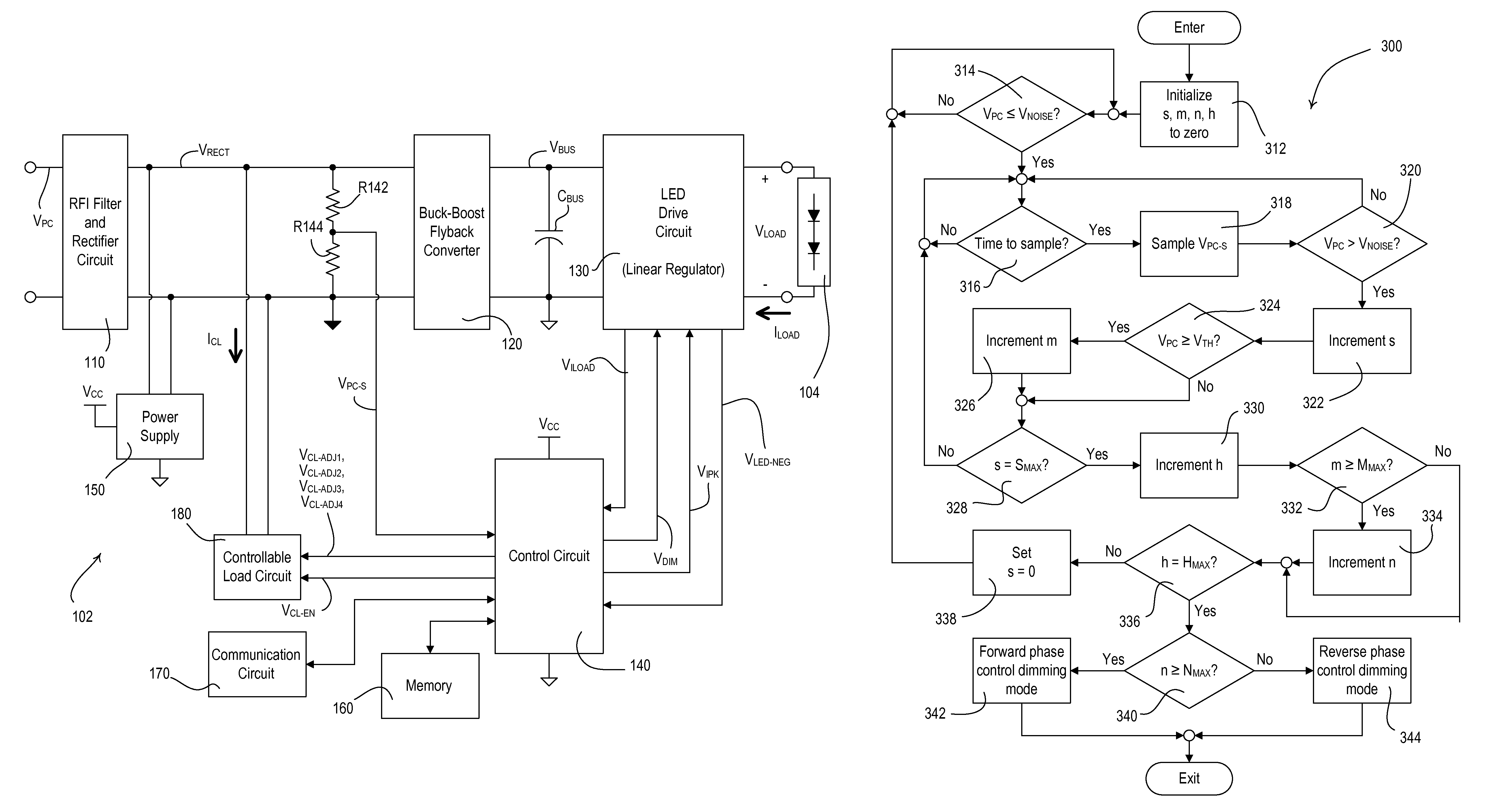
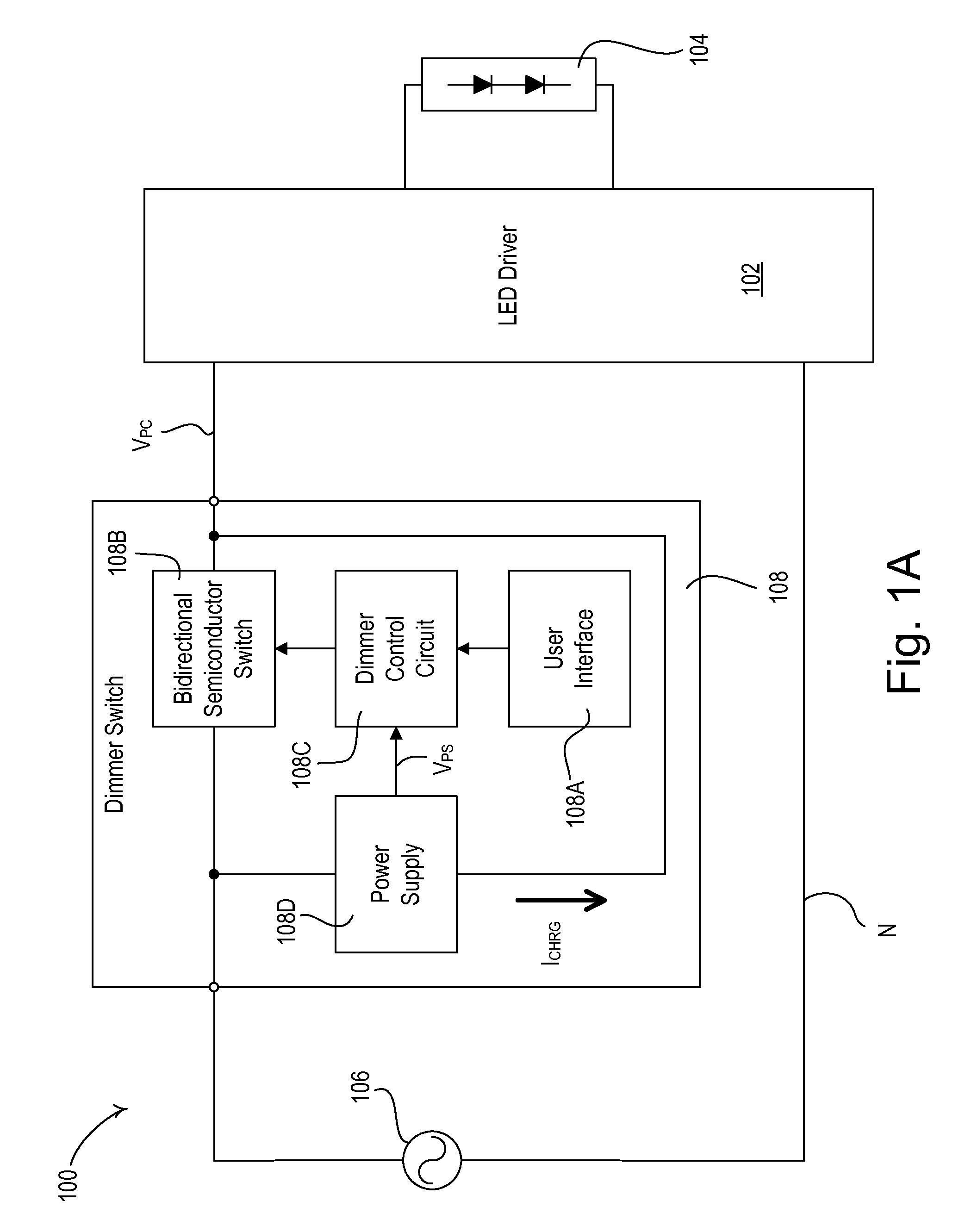
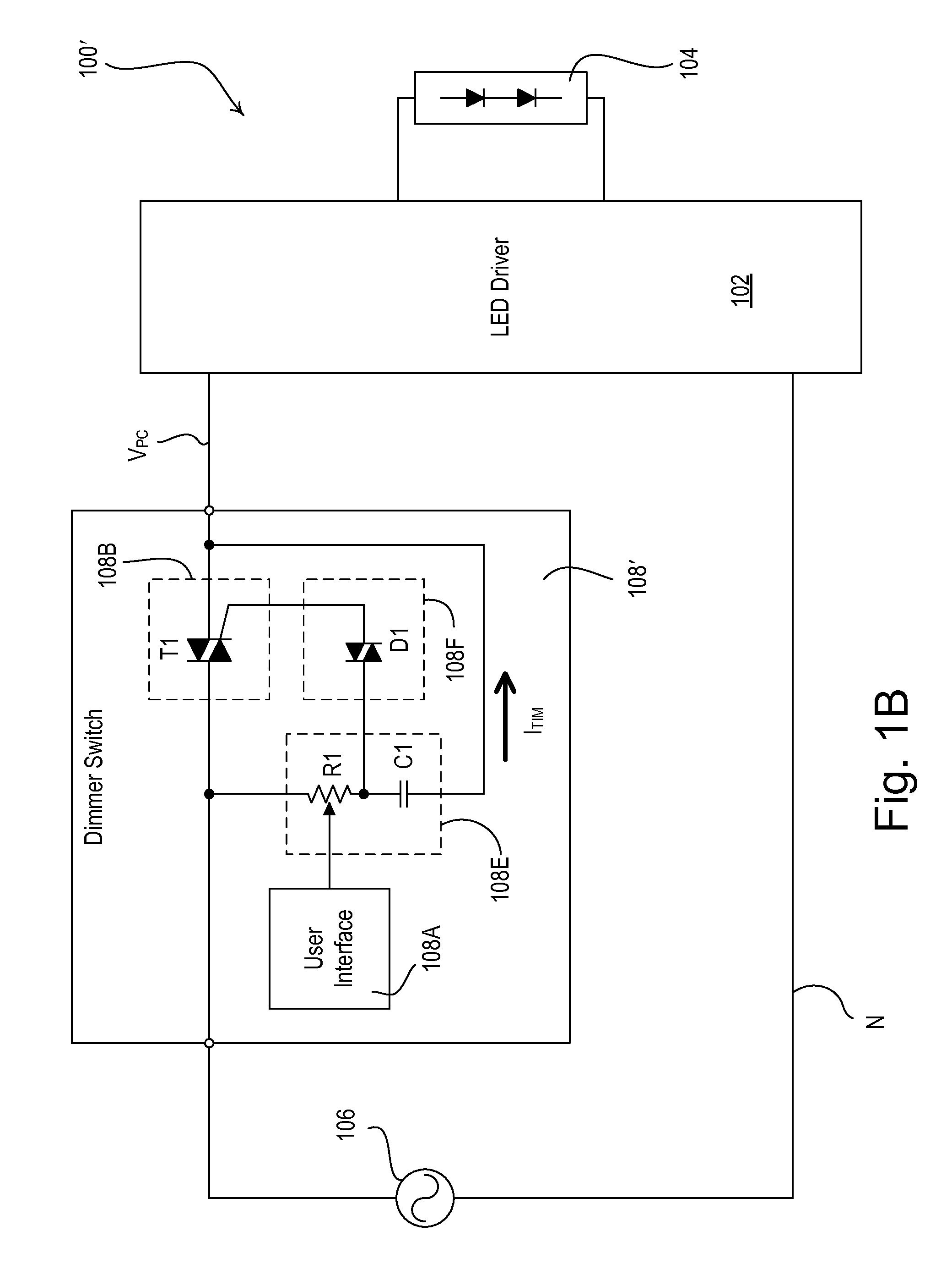
[0036]FIG. 1A is a simplified block diagram of a load control system 100 including a light-emitting diode (LED) driver 102 for controlling the intensity of an LED light source 104 (e.g., an LED light engine) according to the present invention. The LED driver 102 is coupled to an alternating-current (AC) power source 106 via a dimmer switch 108 (e.g., a two-wire “digital” or “smart” dimmer switch as shown in FIG. 1A). The dimmer switch 108 as shown in FIG. 1A does not require a connection to the neutral side N of the AC power source 106. Alternatively, the dimmer switch 108 may comprise a three-wire dimmer switch which would require a connection to the neutral side N of the AC power source. The dimmer switch 108 generates a phase-control voltage VPC (e.g., a dimmed-hot voltage), which may comprise a forward phase-control waveform, i.e., a leading-edge phase-control voltage (as shown in FIG. 2A), or a reverse phase-control waveform, i.e., a trailing-edge phase-control voltage (as show...

third embodiment

[0074]According to the present invention, the LED drivers 102A, 102B, and 102C may be operable to communicate with one another via the respective communication circuit 170 in order to reduce the total current conducted through the thyristor of the dimmer switch 108 to the lowest magnitude. For example, the LED drivers 102A, 102B, 102C may be operable to transmit and receive digital messages via a communication link (not shown), such as a wired communication link or a wireless communication link, for example, a radio-frequency (RF) communication link or an infrared (IR) communication link. Examples of a load control system having a communication link are described in greater detail in co-pending, commonly-assigned U.S. patent application Ser. No. 11 / 644,652, filed Dec. 22, 2006, entitled METHOD OF COMMUNICATING BETWEEN CONTROL DEVICES OF A LOAD CONTROL SYSTEM, and in U.S. Pat. No. 5,905,442, issued May 18, 1999, entitled METHOD AND APPARATUS FOR CONTROLLING AND DETERMINING THE STATUS...

fifth embodiment

[0090]According to the present invention, the LED drivers 102A, 102B, 102C may be operable to determine a total number NTOTAL of LED drivers in the load control system 500 by transmitting and receiving digital messages via a discovery process that is executed, for example, upon power-up. Then, each LED driver 102A, 102B, 102C can determine the appropriate magnitude of the constant current ICL-CNST of the controllable-load current ICL that each of the LED drivers should conduct, such that the magnitude of the total current conducted through the thyristor of the dimmer switch 108 will exceed the rated latching and holding currents of the thyristor. For example, each of the LED drivers 102A, 102B, 102C may control the magnitude of the respective constant current ICL-CNST as a function of the maximum current ICL-MAX and the total number NTOTAL of LED drivers in the load control system 500, e.g.,

ICL-CNST=ICL-MAX / NTOTAL.  (Equation 2)

Accordingly, the magnitude of the total current conduct...


PUM


Abstract

A load control device for controlling the amount of power delivered from an AC power source to an electrical load is operable to conduct enough current through a thyristor of a connected dimmer switch to exceed rated latching and holding currents of the thyristor. The load control device comprises a controllable-load circuit operable to conduct a controllable-load current through the thyristor of the dimmer switch. The load control device disables the controllable-load circuit when the phase-control voltage received from the dimmer switch is a reverse phase-control waveform. When the phase-control voltage received from the dimmer switch is a forward phase-control waveform, the load control device is operable to decrease the magnitude of the controllable-load current so as to conduct only enough current as is required in order to exceed rated latching and holding currents of the thyristor.

Description

CROSS-REFERENCE TO RELATED APPLICATION[0001]This application claims priority from commonly-assigned U.S. Provisional Patent Application Ser. No. 61 / 263,204, filed Nov. 20, 2009, entitled CONTROLLABLE-LOAD CIRCUIT FOR USE WITH A LOAD CONTROL DEVICE, the entire contents of which is hereby incorporated by reference.BACKGROUND OF THE INVENTION[0002]1. Field of the Invention[0003]The present invention relates to a load control device for a high-efficiency light source, such as a light-emitting diode (LED) light source or a compact fluorescent lamp, and more particularly, to a controllable-load circuit for use in an LED driver for controlling the intensity of an LED light source.[0004]2. Description of the Related Art[0005]Light-emitting diode (LED) light sources are often used in place of or as replacements for conventional incandescent, fluorescent, or halogen lamps, and the like. LED light sources comprise a plurality of light-emitting diodes mounted on a single structure and provided ...

Claims


Application Information

Patent Timeline
Patent Type & Authority Patents(United States)
IPC IPC(8): H05B37/02H05B33/08H05B44/00
CPCH05B33/0815H05B37/0245H05B33/0848H05B33/0824H05B45/14H05B45/44H05B47/175H05B45/3725H05B45/10H02M1/082H02M5/2576
Inventor SALVESTRINI, CHRISTOPHER JAMESBEDELL, RYAN S.HARTE, MATTHEW V.
Owner LUTRON TECH CO LLC
Why Eureka
Try Eureka