Portable carrier for holding bags or holding displays on vehicles

Inactive Publication Date: 2015-12-29
ANGARA SIDDHARTHA
View PDF48 Cites 4 Cited by
  • Summary
  • Abstract
  • Description
  • Claims
  • Application Information

AI Technical Summary

Benefits of technology

[0015]It is, therefore, a first object of the present invention to provide methods and apparatuses that hold trash containers preferably on the exterior of a vehicle for conveniently transporting trash from a residence, business or office to a trash collection venue for disposal.
[0017]It is a third object of the present invention to provide portable apparatuses that are readily attachable to, and removable from, a vehicle.
[0018]It is a fourth object of the present invention to provide apparatuses that are capable of being adapted to virtually any vehicle.

Problems solved by technology

While the general methods of transporting trash bags, including travelling by foot or a vehicle, are relatively simple for individuals residing nearby the garbage disposal venue, they can be challenging for the ones residing farther away.
The quantity, type, size, weight, shape and grips of trash bags can make the task more challenging, particularly when travelling by foot.
When they are placed inside a vehicle, for instance in the trunk or inside of a car itself, any leak can stain the interiors in addition to the possibility of leaving behind an unpleasant odor.
Though there are a few devices which were developed to assist in transporting trash bags to a garbage disposal venue for disposal, the inadequacy of appropriate apparatuses and methods to do so conveniently and efficiently makes this commonest of chores a challenge even today.
However, the fact that using the device necessitates its placement over a door frame or an open window presents several drawbacks.1. It makes it very inconvenient to enter or exit the vehicle through the door on which the garbage bag is hung.2. The device cannot be used for trash bags which do not have looped grips to hang the bags.3. The trash bag can limit outside visibility for the driver, and passengers, which could compromise safety.4. In warm, cold or rainy weather conditions, an open window with garbage bags hung on it can expose the passengers inside to external precipitation, unfavorable temperatures and any unpleasant odor emanating from the trash.5. Hanging heavy trash bags over the window glass can damage the glass-roller assembly by putting undue load on it.6. Configuring the device in place for, and removing it after, each use not only demands extra effort but also increases the likelihood of misplacing the device as there is no specific provision made for storing it in a particular place.7. From an appearance standpoint, driving a vehicle with trash bags hanging over the windows on either side can be unsightly and aesthetically undesirable.
And the requirement to keep the trunk lid closed when towing the cart may be undesirable when, for instance, an oversized container is also to be transported in the trunk.
Furthermore, the device cannot be easily stored inside a vehicle.

Method used


Image

  • Portable carrier for holding bags or holding displays on vehicles
  • Portable carrier for holding bags or holding displays on vehicles
  • Portable carrier for holding bags or holding displays on vehicles

Examples


first embodiment

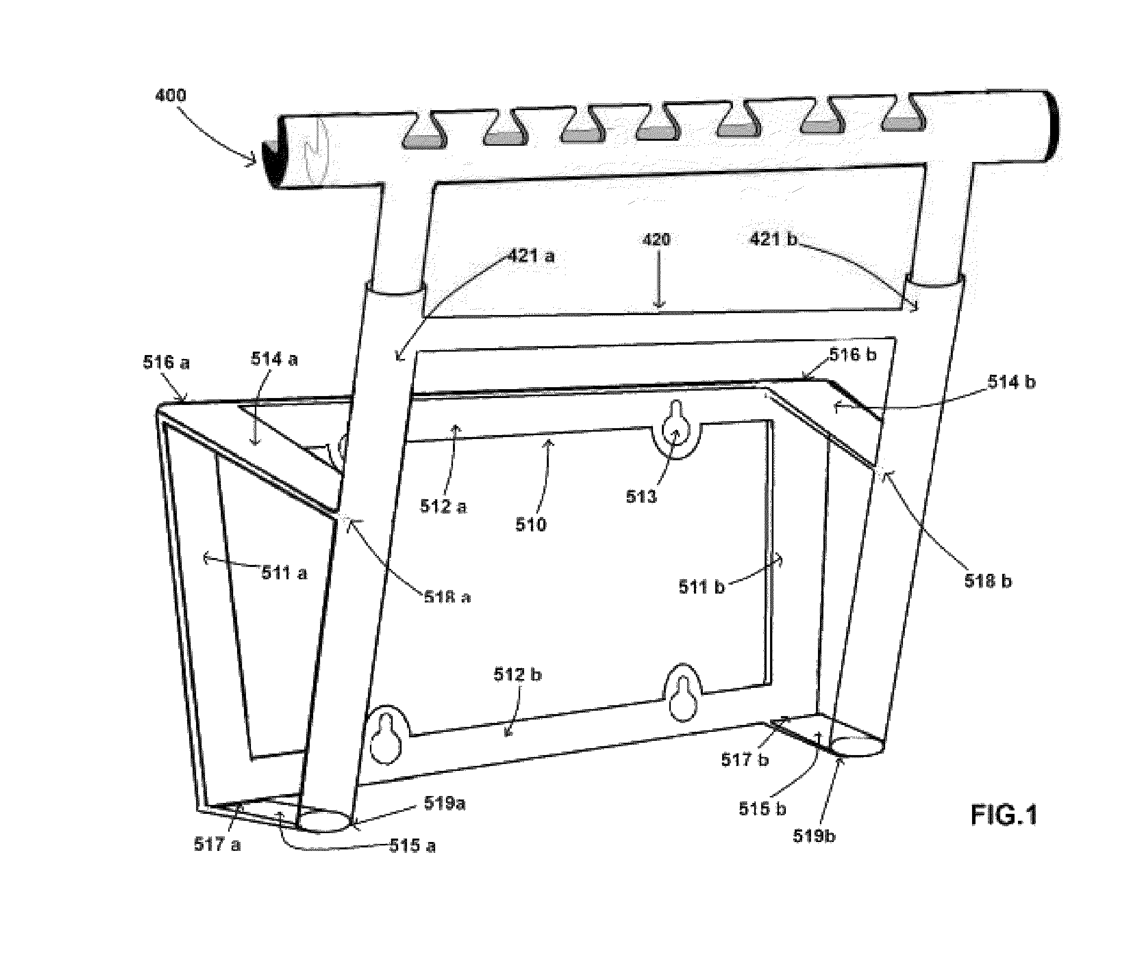
[0105]In a first embodiment, the receiver segment 420 is attached to an engagement segment 510 of FIG. 1 using two long strips 514a and 514b and two short strips 514c and 514d at points 516a, 516b, 517a and 517b of the engagement segment and 518a, 518b, 519a and 519b of the receiver segment respectively. The long strips 514a and 514b attached to 510 are sufficiently angled so as to not obstruct mounting of the apparatus when the license plate on a vehicle is not vertical. The angle of inclination of the license plate from the vertical plane matches the angle of inclination of the long strips 514a and 514b. The engagement segment 510 is a rectangular frame with two vertical flat strips 511a and 511b and two horizontal flat strips 512a and 512b. The horizontal strips 512a and 512b each has one or more, preferably two, keyholes 513 which are aligned with the through holes 151 of a license plate 150 in FIG. 13. The keyholes comprise a lower circular portion and an upper elongated portio...

second embodiment

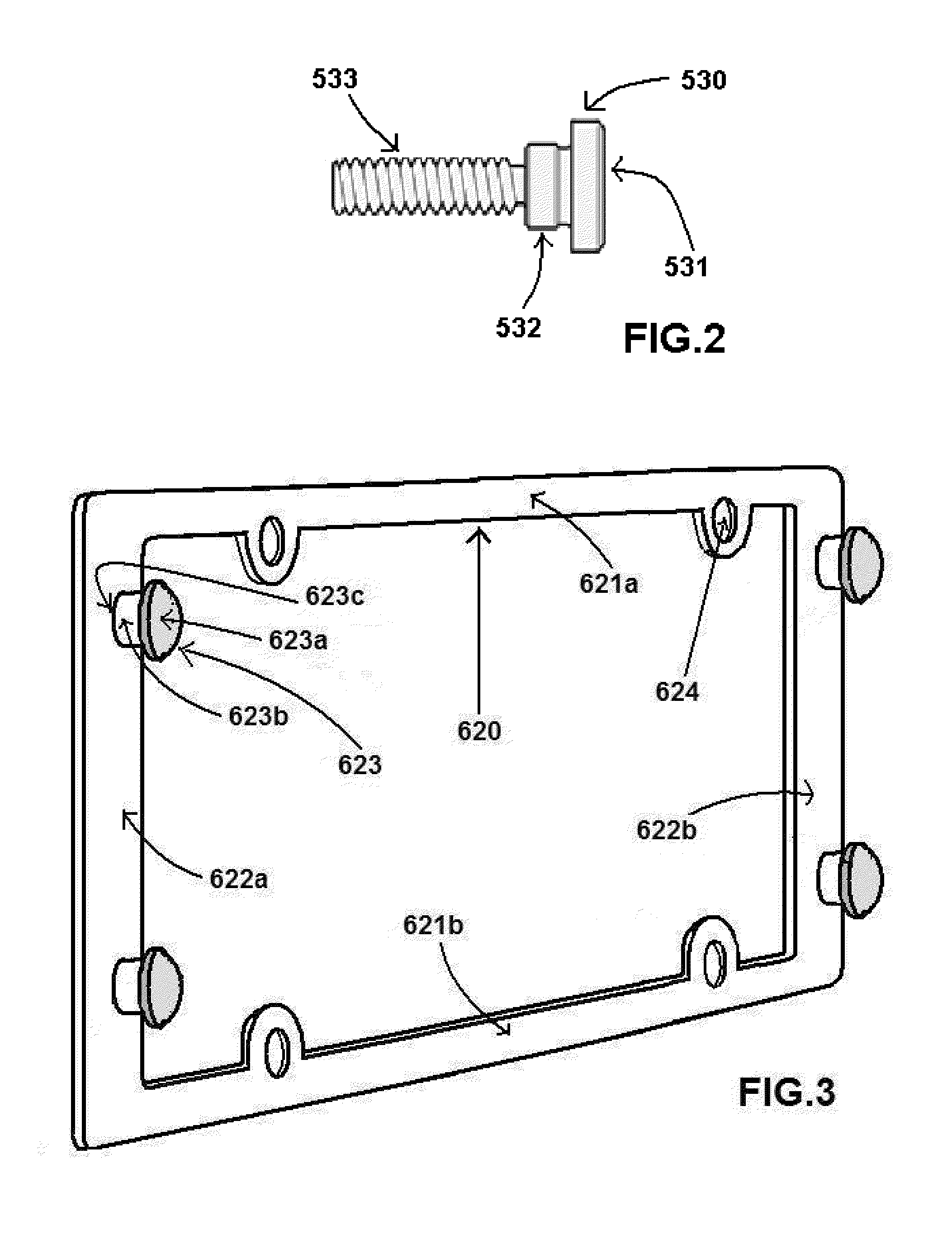
[0106]In a second embodiment, the receiver segment 420 is attached to an engagement segment (612a, 612b) of FIG. 5 using two long strips 611a and 611b and two short strips 613a and 613b at points 618a, 618b, 619a and 619b of the engagement segment and 616a, 616b, 617a and 617b of the receiver segment respectively. The long strips 611a and 611b attached to the engagement segment (612a, 612b) are sufficiently angled so as to not obstruct mounting of the apparatus when the license plate on a vehicle is not vertical. The angle of inclination of the license plate from the vertical plane matches the angle of inclination of the long strips 611a and 611b. The two vertical flat strips 612a and 612b of the engagement segment each has one or more, preferably two, keyholes 614 which are aligned with the shoulders 623 of an adapter 620 in FIG. 3. The keyholes comprise a lower circular portion and an upper elongated portion, and engage the shoulders of an adapter which is bolted atop a license pl...

third embodiment

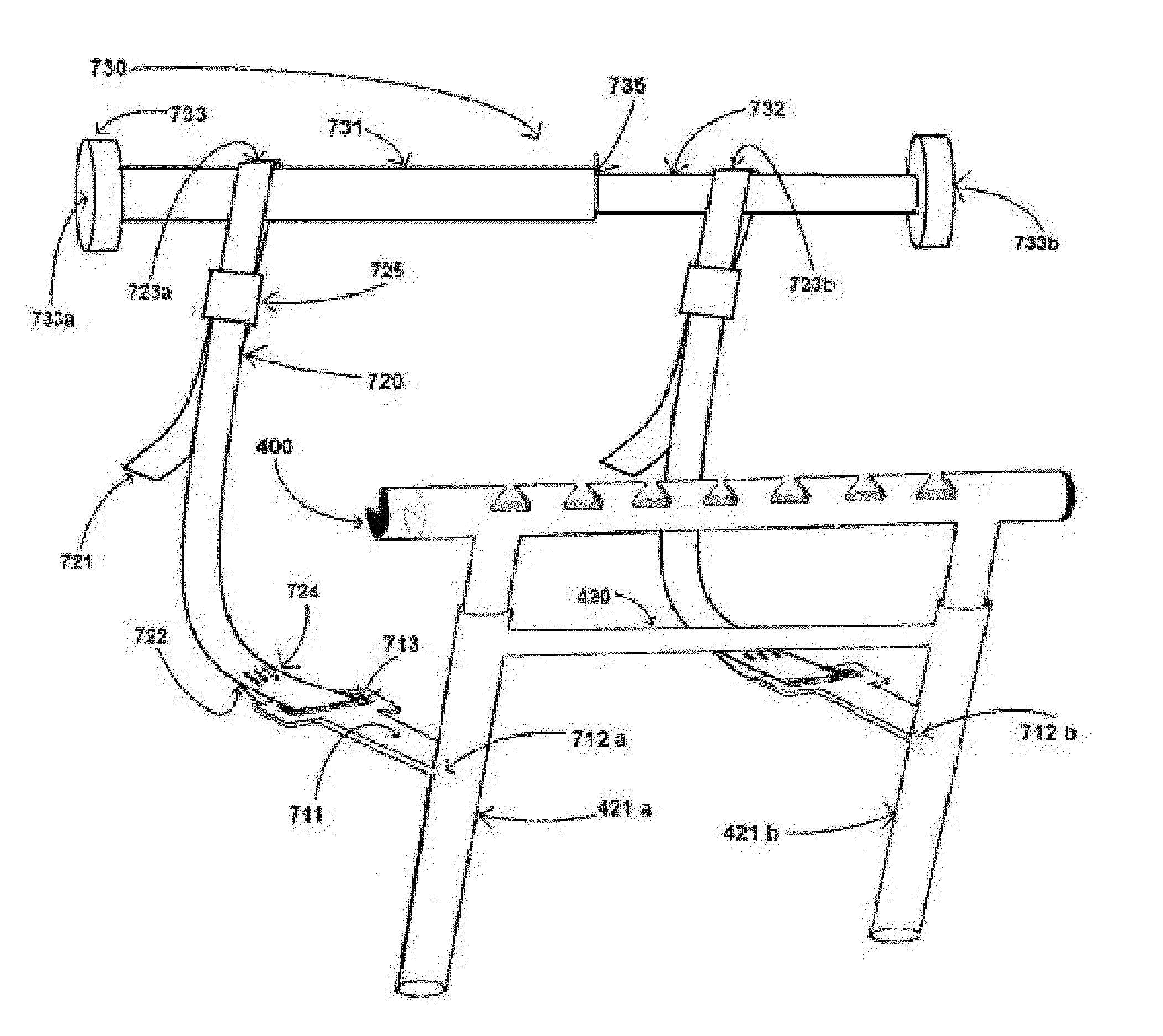
[0107]In a third embodiment, an engagement segment comprising one or more but preferably two long strips 711 is attached to the receiver segment 420. As shown in FIG. 6, one end of each strip 711 has a strap eyelet 713 and the other end is attached, preferably at about a 90 degree angle, to the receiver segment 420 at points 712a and 712b on rods 421a and 421b respectively. The eyelets 713 are wide enough for a strap 720 to pass through. One or more but preferably two waterproof straps 720, each having a proximal end 721 and a distal end 722, link the rack to the restraining bar 730. The straps are strong enough to support the rack, and any trash bags mounted on it, on the exterior of a vehicle. Also, the straps are thin enough to fit in the gap between the bottom 125 of the closed trunk door and bottom bridge 124 of the door frame of a vehicle 100 in FIG. 13. Nylon or polyester webbings are good examples of such a strap. The distal ends 722 of the straps are looped through the eyel...


PUM

PropertyMeasurementUnit
angleaaaaaaaaaa
angleaaaaaaaaaa
angleaaaaaaaaaa

Abstract

Apparatuses and related methods for holding bags for transporting trash or holding displays on the exterior of a vehicle. The apparatuses include an adjustable-size rack comprising one or more detachable members which are attachable to the receiver segment of a base member. A base member has an engagement segment for mounting the apparatus on a vehicle. In a first apparatus, the engagement segment mounts on the shoulders of the shoulder bolts used for installing the license plate on a vehicle. In a second apparatus, the engagement segment mounts on the shoulders of an adapter which is installed over the license plate of a vehicle. In a third apparatus, two straps link the engagement segment on the exterior to a restraining bar configured inside the trunk of a vehicle. In a fourth apparatus, the engagement segment mounts on an external spare wheel of a vehicle.

Description

BACKGROUND OF THE INVENTION[0001]1. Field of the Invention[0002]The present invention relates to the transportation of containers, and more particularly the methods and apparatuses for mounting and transporting trash for disposal by a vehicle.[0003]2. Description of the Related Art[0004]In many residential communities and business locations, trash is required to be disposed off in a garbage collection facility or a similar designated area from where it is picked up by a garbage disposal service. Typically, trash is collected in a can or a similar receptacle lined with a disposable trash bag. Alternatively, trash may also be collected in plastic carry bags or similar containers. Most trash bags are equipped with drawstring loops, handles or tie-extensions, among similar provisions, which are tied with each other into a knot to shut the bag and which also serve as grips to hold or hang the bag. If there is no specific provision made to tie a bag, the opposite edges of the bag can be p...

Claims


Application Information

Patent Timeline
Patent Type & Authority Patents(United States)
IPC IPC(8): B60R9/06B60R13/10
CPCB60R13/105B60R9/06Y10T29/49716
Inventor ANGARA, SIDDHARTHA
Owner ANGARA SIDDHARTHA
Why Eureka
Try Eureka