Needle placement manipulator with two rotary guides

a technology of manipulators and needles, applied in the field of medical devices, can solve the problems of long trial and error routines, affecting the function of the patient, and affecting the patient,

Active Publication Date: 2015-12-29
CANON USA +1
View PDF45 Cites 23 Cited by
  • Summary
  • Abstract
  • Description
  • Claims
  • Application Information

AI Technical Summary

Problems solved by technology

This process often requires a lengthy trial and error routine, which can be deleterious to the patient.
The device can be placed on the skin or on near an exposed organ of a patient, but its function can be jeopardized by movement.
In MRI-guided percutaneous interventions, accurate needle placement is of great concern and of considerably more difficulty that in needle placement systems for other modalities, such as CT or ultrasound.
But rigidity of arc-shaped arm is low, and in particular rigidity of arc-shaped guides including attached motor is also low.
Arc-shaped arms provide visibility, so that a clinician can see the needle entry point, but opening is too small to access the entry point.

Method used


Image

  • Needle placement manipulator with two rotary guides
  • Needle placement manipulator with two rotary guides
  • Needle placement manipulator with two rotary guides

Examples


first embodiment

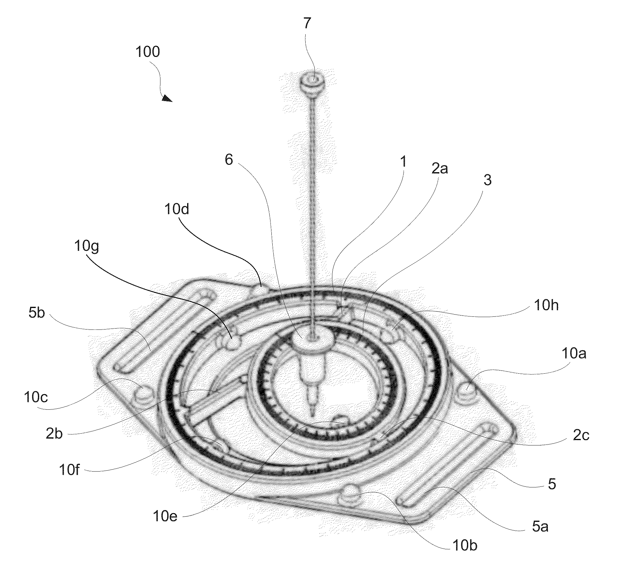
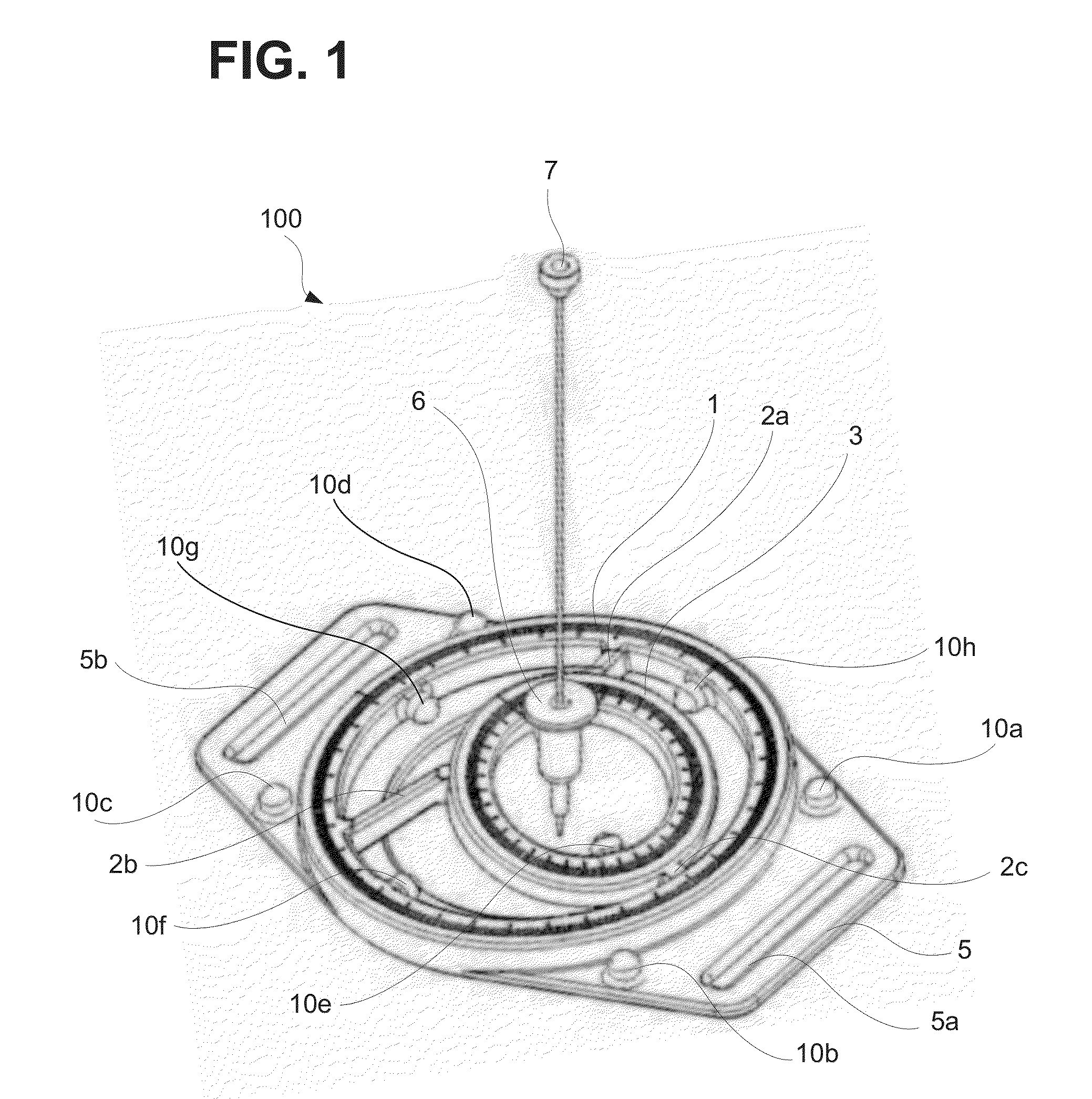
[0037]As illustrated in FIG. 1, a needle placement manipulator 100 includes two circular ring-shaped rotary guides (hereinafter referred simply to as “rotary guides”), which are arranged in a slanted orientation with respect to each other atop a base body 5. Specifically, a first rotary guide 1 and a second rotary guide 3 are arranged in a slanted orientation with respect to each other. The two rotary guides 1 and 3 are supported by a base body 5. The base body 5 is preferably a non-magnetic structure configured to be mounted on a patient's skin 8. As discussed in more detail below, the base body 5 and certain other elements can be manufactured of disposable and recyclable materials, such as plastics and / or composites thereof. The first rotary guide 1 is supported by the base body 5 and connects to a first rotation body 2. The second rotary guide 3 is supported by the first rotation body 2 and connects to a second rotation body 4. The second rotation body 4 is configured to support...

second embodiment

[0070]FIG. 6B illustrates a variation of the second embodiment where, in the first rotation drive unit 210, a light source fiber fs1 delivers light to the rotary scale 18 and a collecting fiber fd1 is used to detect light reflected from the rotary scale 18. Similarly, in the second rotation drive unit 220, a light source fiber fs2 delivers light to the rotary scale 28 and a collecting fiber fd2 is used to detect light reflected from the rotary scale 28. The use of optical fibers may be particularly desirable to avoid the use of electrical wiring for minimizing noise and interference in the MRI system, in particular to avoid interference with RF-pulse signals.

[0071]Advantageously, in the second embodiment, accurate positioning up to an order of microns can be implemented by the use of optical rotary position sensors and piezoelectric actuators. Accurate positioning is available by piezoelectric actuator and feedback signaling, which can be automated by controllers operated with progr...

third embodiment

[0078]FIG. 8B illustrates a perspective view of the manipulator 300 mounted onto RF-coil 32 in which a sectional cut along vertical plane H-H is performed. FIG. 9A illustrates a sectional view of the needle placement manipulator cut along a vertical plane H-H, according to the The first attachment 30 includes a flat setting portion on which the RF-coil 32 is set, and a circular projection portion 30a configured to engage with the second attachment 31. Similarly, the second attachment 31 includes a flat setting portion below which the RF-coil is set, and a circular projection portion 31a which engages with the projection portion 30a of the first attachment 30.

[0079]As illustrated in FIG. 9A, the single loop RF-coil 32 is placed with the circular projection 30a of attachment 30 going through the opening of the RF-coil 32. The second attachment 31 is fixed to the base body 5 and the circular projection section 31a is disposed at the bottom surface thereof. These two attachments 30 and...


PUM


Abstract

A needle placement manipulator includes, a pair of rotary guides arranged at a slanted angle with respect to each other, a needle holder which holds a needle along a needle holder axis, and a base body on which the guides are supported. The needle holder axis and each axis of the rotary guides cross at a single point located at or below the base body. The base body is configured to be attached to a patient or to an RF-coil.

Description

BACKGROUND[0001]1. Field[0002]The disclosure of this application relates generally to medical devices, and in particular it relates to a needle placement manipulator with two rotary guides slanted with respect to each other, and to a needle guidance system equipped with the needle placement manipulator.[0003]2. Related Art[0004]The use of imaging modalities, such as ultrasound, mammography, computed tomography (CT), Magnetic Resonance Imaging (MRI) and the like, to assist in identifying and treating abnormalities within the body of a patient, has gained increased acceptance in the medical field. The above-named and other imaging modalities generally provide good contrast between different soft tissues of the body. Thus, many of these techniques are being used to depict the boundaries of damaged tissue within healthy tissue for accurate identification and treatment. Advanced diagnostic procedures, however, require further validation and refinement in localization of damaged tissue. T...

Claims


Application Information

Patent Timeline
Patent Type & Authority Patents(United States)
IPC IPC(8): A61B5/05G01R33/28A61B19/00
CPCG01R33/286A61B19/201A61B2019/4857A61B19/2203A61B34/30A61B90/11A61B2090/0811A61B17/3403A61B2017/3409
Inventor FUJIMOTO, KOSUKEARIMITSU, YASUMICHIHATA, NOBUHIKOSONG, SANG-EUNTOKUDA, JUNICHI
Owner CANON USA
Why Eureka
Try Eureka