Electrical connector

a technology of electrical connectors and connectors, applied in the direction of coupling contact members, coupling device connections, soldered/welded conductive connections, etc., can solve the problems of electrical connectors becoming buckled, reduce the resistance of operators' hands, reduce the size of electrical connectors, and improve the effect of insertability

Active Publication Date: 2015-12-29
IRISO ELECTRONICS CO LTD
View PDF19 Cites 11 Cited by
  • Summary
  • Abstract
  • Description
  • Claims
  • Application Information

AI Technical Summary

Benefits of technology

[0006]An object of the present invention is to provide an electrical connector that can reduce a resistance that an operator feels with his / her hand when terminals of the electrical connector become fitted with a connection object and that can improve the insertability. Another object of the present invention is to provide an electrical connector that can make a rear contact-point portion to securely contact a connection object and that has high reliability.
[0009]Therefore, in the present invention, the positions of the front contact-point portions that are adjacent to each other and the positions of adjacent the rear contact-point portions that are adjacent to each other are respectively displaced from each other so that the rear contact-point portions contact the connection object at different positions in the insertion direction. Thus, the number of the rear contact-point portions that simultaneously contact the connection object can be reduced and the insertion force can be dispersed, and therefore the insertability can be improved. Accordingly, occurrence damage to the terminal due to imperfect fitting, such as semi-fitting and oblique fitting described above, and due to buckling can be reduced.
[0011]Moreover, according to the present invention, the front contact-point portion slidably contacts the conductively contact portion of the connection object, and the rear contact-point portion slides along a sliding path of the front contact-point portion in an insertion direction in which the connection object is inserted into the movable housing and conductively contacts the conductive connection portion from which the foreign substance has been wiped off by the front contact-point portion. Therefore, the rear contact-point portion can conductively contact the connection object stably without foreign substances interposed therebetween, and the contact reliability can be increased.
[0012]Furthermore, according to the present invention, the base and the movable portion are connected to each other in the fixed housing and are arranged side by side in the fixed housing in such a way that the base and the movable portion extend in the insertion direction. Accordingly, the size of the electrical connector having the floating function can be reduced in the transverse direction of the electrical connector perpendicular to the direction in which the terminals are arranged at a pitch.
[0014]In this case, the rear contact-point portion, which is located deeper in the insertion direction of the connection object than the front contact-point portion, can securely contact the connection object.
[0015]With the electrical connector according to the present invention, a resistance that an operator feels with his / her hand can be reduced and the insertability can be improved while realizing a function of wiping off foreign substances adhering to a connection object, a floating function, and reduction in the size of an electrical connector in the transverse direction. Thus, occurrence of imperfect fitting, such as semi-fitting and oblique fitting, can be suppressed. Moreover, damage to a terminal due to buckling or the like can be suppressed. Accordingly, with the electrical connector according to the present invention, the rear contact-point portion can securely contact a connection object and therefore an electrical connector having high reliability can provided.

Problems solved by technology

Moreover, if the operator tries to forcibly and clumsily insert the connection object into the electrical connector with a large force against the resistance to his / her hand, the connection object may become obliquely fitted into the electrical connector or the electrical connector may become buckled.

Method used


Image

  • Electrical connector
  • Electrical connector
  • Electrical connector

Examples


Embodiment Construction

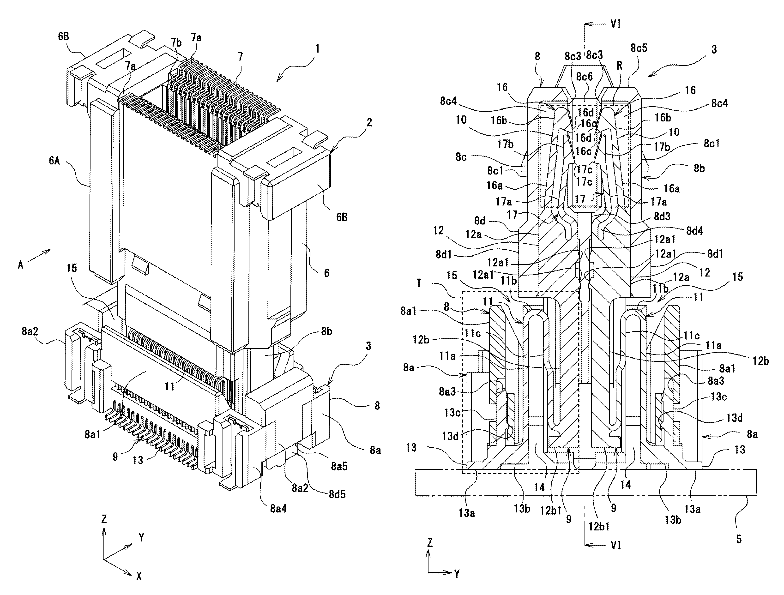
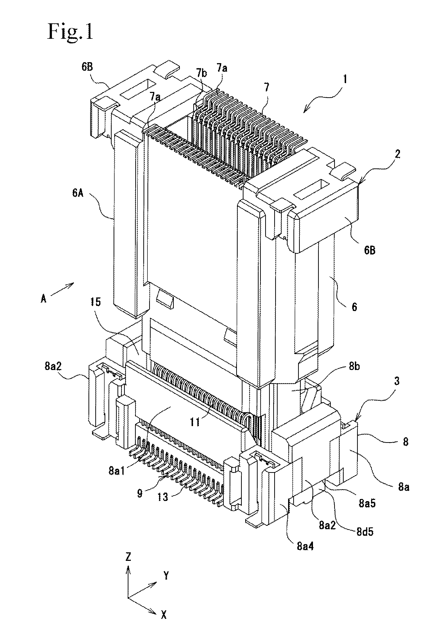
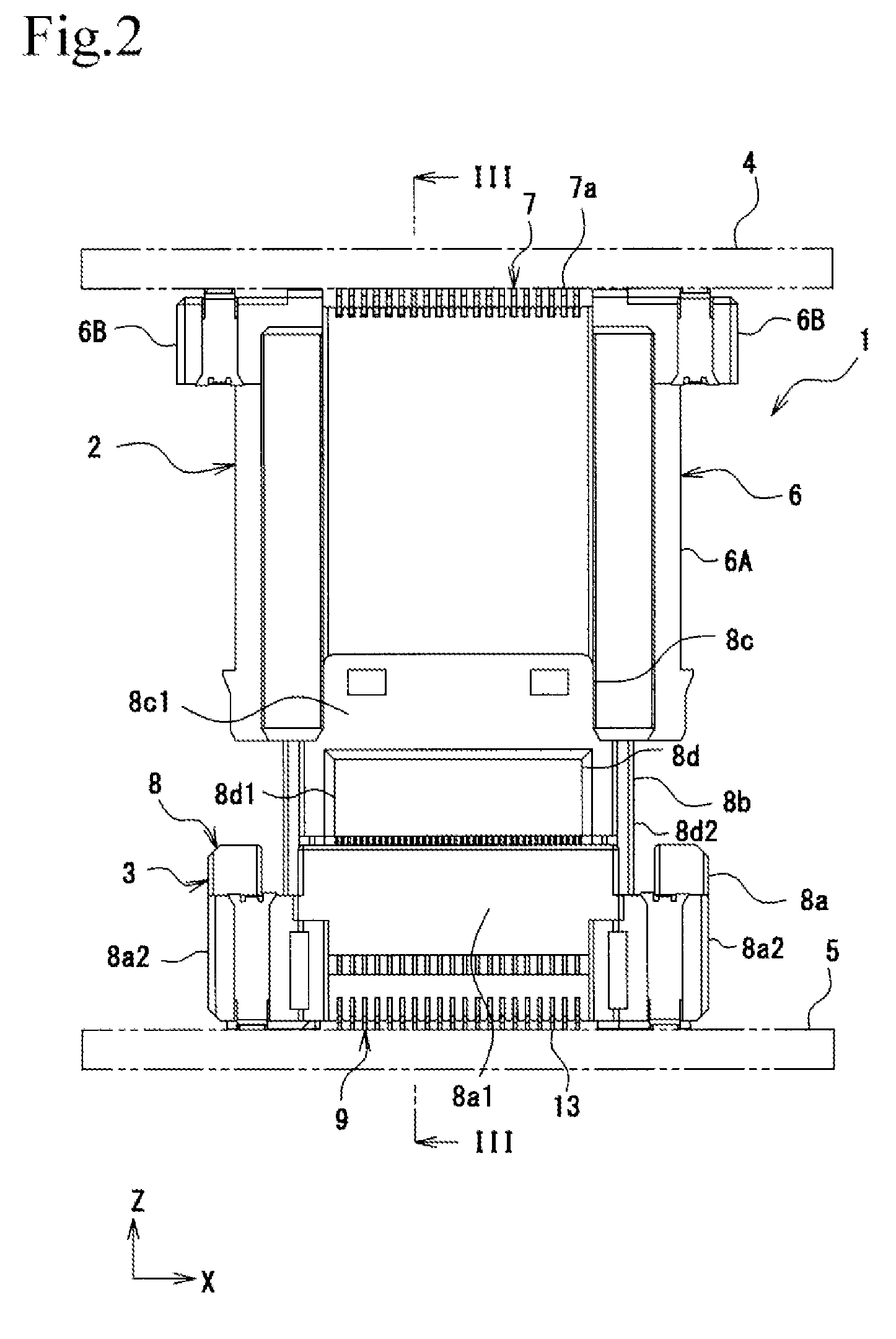
[0029]Hereinafter, an embodiment of an electrical connector according to the present invention will be described with reference to the drawings. In the embodiment below, an example of an interboard connector having a floating function will be described.

[0030]As illustrated in FIGS. 1 and 2, an electrical connector 1 includes a plug connector 2 and a socket connector 3. As illustrated in FIGS. 2 to 5, the plug connector 2 is mounted on a board 4, and the socket connector 3 is mounted on a board 5. When the plug connector 2 is fitted into the socket connector 3, the board 4 and the board 5 become conductively connected to each other.

[0031]As illustrated in FIGS. 1 to 13, in the specification, claims, and the drawings, the longitudinal direction of the electrical connector 1 will be referred to as the X direction, the transverse direction of the electrical connector 1 will be referred to as the Y direction, and the insertion / extraction direction in which the plug connector 2 is inserte...


PUM


Abstract

An electrical connector includes a socket housing and socket terminals. Each socket terminal includes a front terminal and a rear terminal. The front terminal contacts a plug connector inserted into the socket housing. The front terminal includes front contact-point portion that contacts the plug connector and an elastic piece that supports the front contact-point portion so as to be elastically displaceable. The rear terminal includes a rear contact-point portion and an elastic piece that supports the rear contact-point portion so as to be elastically displaceable. The rear contact-point portion contacts the plug connector after the front contact-point portion has contacted the plug connector. The front contact-point portion and the elastic piece, and the rear contact-point portion and the elastic piece are each formed so as to maintain a plate surface of a flat metal plate.

Description

BACKGROUND OF THE INVENTION[0001]1. Field of the Invention[0002]The present invention relates to an electrical connector that contacts and becomes conductively connected to a connection object, such as an electrical connector, a board, or a flat cable.[0003]2. Description of the Related Art[0004]As the performance and multifunctionality of automobile electronic appliances and consumer electronic appliances have increased, electrical connectors for connecting printed circuit boards (hereinafter, referred to as “boards”) to each other are increasingly used. Moreover, as electronic appliances have been reduced in size, boards have also been reduced in size and component packing density has increased. At the same time, as the types of data processing operations have increased with increasing performance and multifunctionality of electronic appliances, the number of terminals of connectors has been increasing (see Japanese Unexamined Patent Application Publication No. 2011-40206).[0005]H...

Claims


Application Information

Patent Timeline
Patent Type & Authority Patents(United States)
IPC IPC(8): H01R12/71H01R4/02H01R12/73H01R13/24H01R12/91
CPCH01R12/716H01R4/028H01R13/2457H01R12/73H01R12/91
Inventor SATO, KATSUMASA
Owner IRISO ELECTRONICS CO LTD
Why Eureka
Try Eureka