
Audio limiter system and method

Active Publication Date: 2015-12-29
IZOTOPE
View PDF8 Cites 22 Cited by
  • Summary
  • Abstract
  • Description
  • Claims
  • Application Information

AI Technical Summary

Benefits of technology

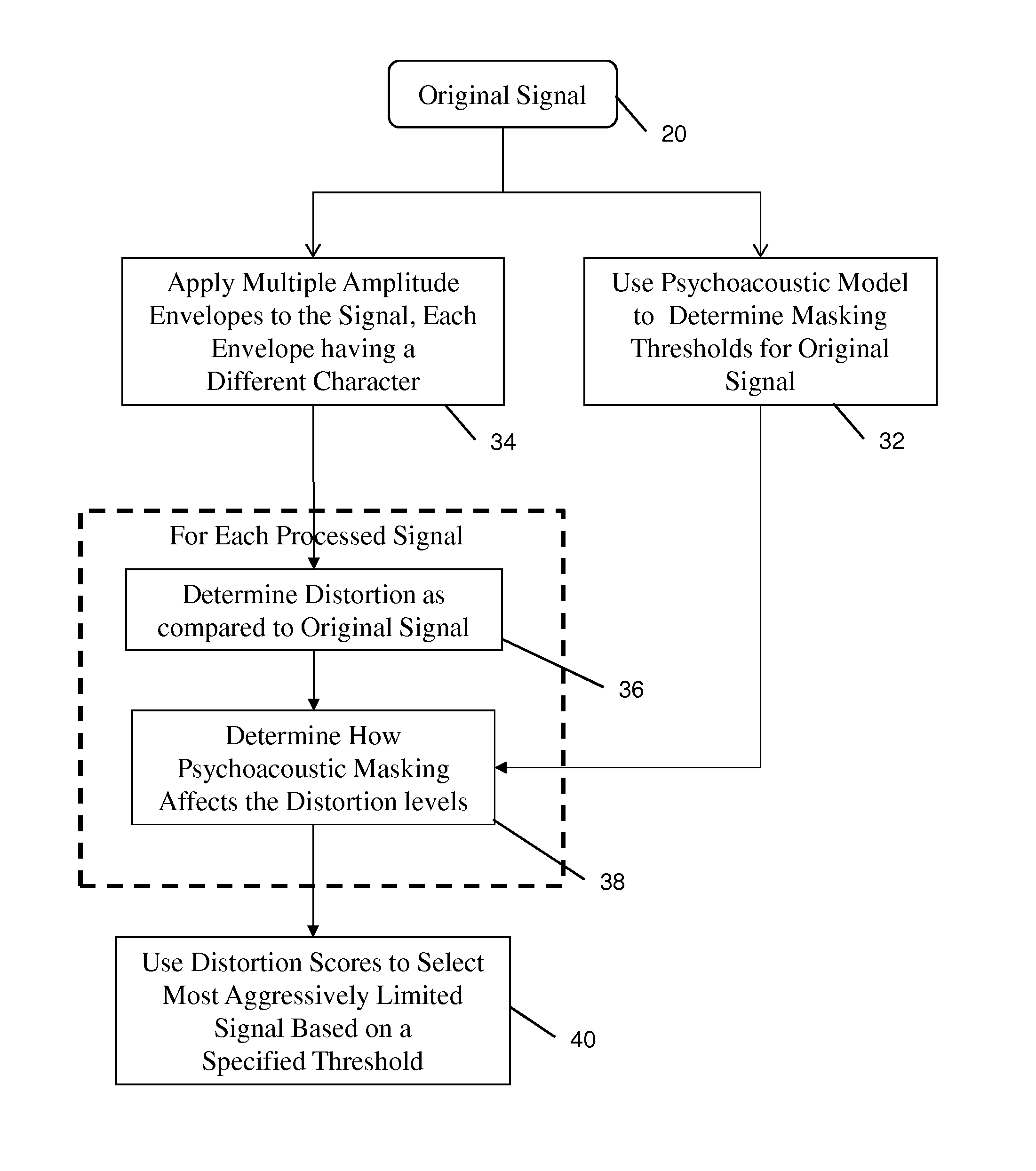
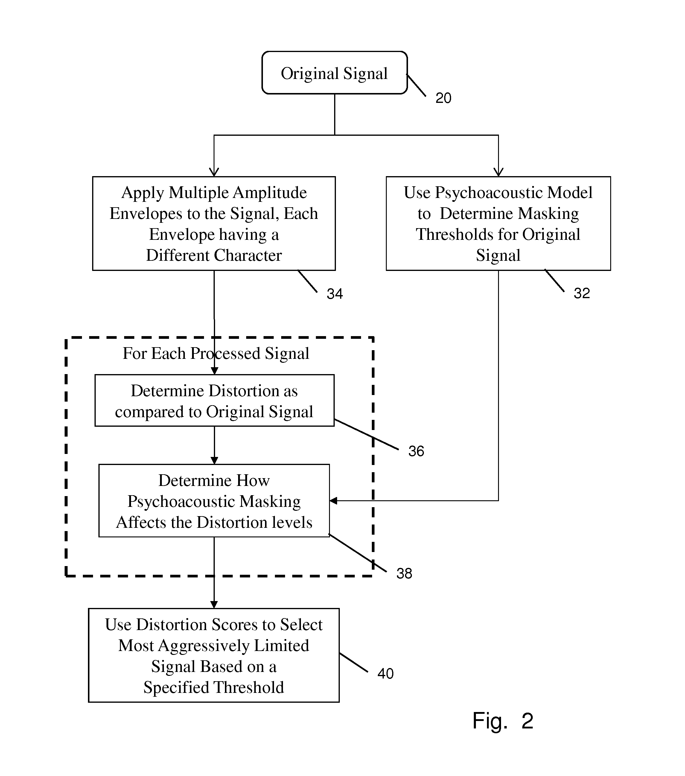
The present invention has a limiter that helps keep the audio signal sound sharp and clear, even when the volume is turned up. The limiter uses a special model to determine how much limiting can be done without causing distortion. This results in a higher quality audio signal.

Problems solved by technology

Clipping is undesirable not only because of the distortion it causes, but also the loss in the data signal may not be recoverable.
Limiters have a disadvantage that if applied aggressively, they can make the audio sound very bad and unnatural.
Based on parameter settings, limiters can cause audible distortion and other unwanted effects, such as pumping.

Method used


Image

  • Audio limiter system and method
  • Audio limiter system and method
  • Audio limiter system and method

Examples


Embodiment Construction

[0019]In the following description of the various embodiments, reference is made to the accompanying drawings, which form a part hereof, and in which is shown by way of illustration various embodiments in which the invention may be practiced. It is to be understood that other embodiments may be utilized and structural and functional modifications may be made without departing from the scope of the present invention.

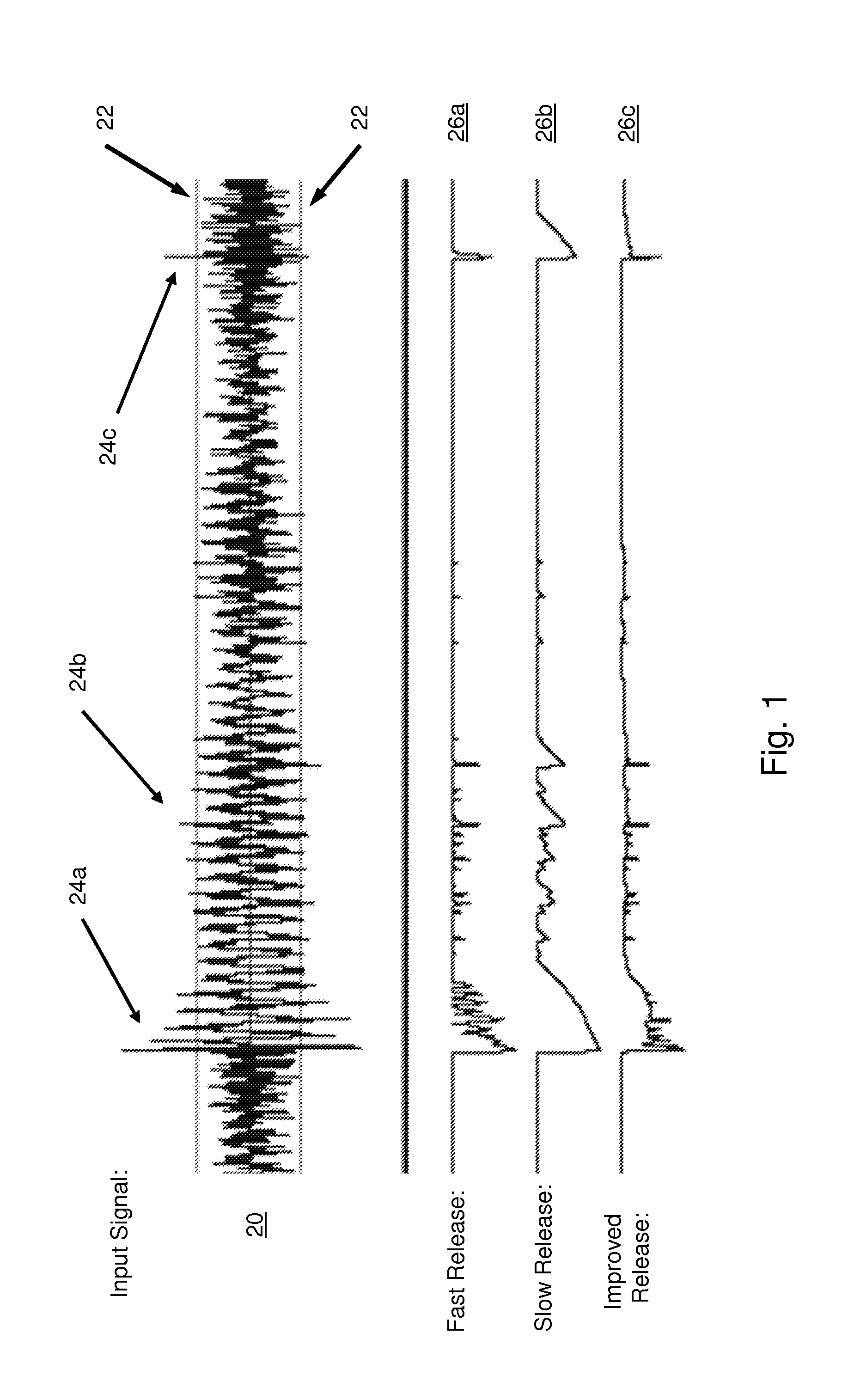
[0020]The operation of a dynamics processor can be generally described as two steps: the processing device detects the input signal level and dynamically adjusts the output level, i.e. applies a certain time-varying gain envelope to the signal. For a high fidelity sound, a few requirements must be maintained. One important requirement is that the gain envelope should be smooth, without breaks or sharp bends. Indeed, if the gain envelope has breaks, then the output signal will have breaks in the waveform, audible as clicks or crackle. Sharp bends in the gain envelope can a...


PUM


Abstract

A system and method for limiting amplitude of a signal, such as limiting the loudness of an audio signal. Embodiments of the present invention allow for the most aggressive limiting by using an advanced psychoacoustic model to intelligently determine the amount of limiting that can be done to the incoming signal before producing distortion that is detectable to the human ear.

Description

[0001]This application claims priority to provisional U.S. Application Ser. No. 61 / 724,052 filed on Nov. 8, 2012, which is fully incorporated herein by reference.FIELD OF THE INVENTION[0002]The invention relates generally to signal processing. More specifically, the invention is directed towards a system and method for compressing and / or limiting audio signals.BACKGROUND OF THE INVENTION[0003]In the fields of audio and music, it is fairly common to apply some type of dynamics processing to audio. Dynamic processing generally focuses on the volume of audio, but not necessarily in a linear fashion. In general, a dynamics processor takes an input audio signal, and produces an output audio signal with the amplitude (volume) adjusted, typically with some time-varying gain.[0004]A common type of dynamics processing is known as compression, wherein the higher the input signal level, the higher the attenuation. Many compressors work using a threshold, in that when the input signal increases...

Claims


Application Information

Patent Timeline
IPC IPC(8): H03G9/20H03G11/00
CPCH03G11/00H03G9/20H03G9/005H03G9/025
Inventor LUKIN, ALEXEY
Owner IZOTOPE
Learn More