
Signal modulation method resistant to echo reflections and frequency offsets

a signal modulation and echo reflection technology, applied in the field of communication protocols and methods, can solve the problems of affecting the stability of the signal, the underlying equipment (i.e. the transmitter and receiver) itself cannot always operate perfectly, and the frequency shift can be produced. , to achieve the effect of improving the signal to noise ratio, improving the radar system, and improving the quality

Active Publication Date: 2015-07-14
COHERE TECH
View PDF3 Cites 256 Cited by
  • Summary
  • Abstract
  • Description
  • Claims
  • Application Information

AI Technical Summary

Benefits of technology

The patent describes a method for improving the quality of signals received in a communication system. The method uses time and frequency deconvolution to analyze the patterns of waveforms in the signals and determine how much distortion is involved. This information helps the receiver determine the relative positions and velocities of the signal sources, and can also assist in automatic system optimization. The method can correct for echo reflections and frequency offsets, resulting in higher quality signals and useful information for various applications, such as radar systems.

Problems solved by technology

These signals, which generally travel at or near the speed of light, can be subjected to various types of degradation or channel impairments.
Additionally, the underlying equipment (i.e. transmitters and receivers) themselves do not always operate perfectly, and can produce frequency shifts as well.
These echo effects and frequency shifts are unwanted, and if such shifts become too large, can result in lower rates of signal transmission, as well as higher error rates.

Method used


Image

  • Signal modulation method resistant to echo reflections and frequency offsets
  • Signal modulation method resistant to echo reflections and frequency offsets
  • Signal modulation method resistant to echo reflections and frequency offsets

Examples


examples

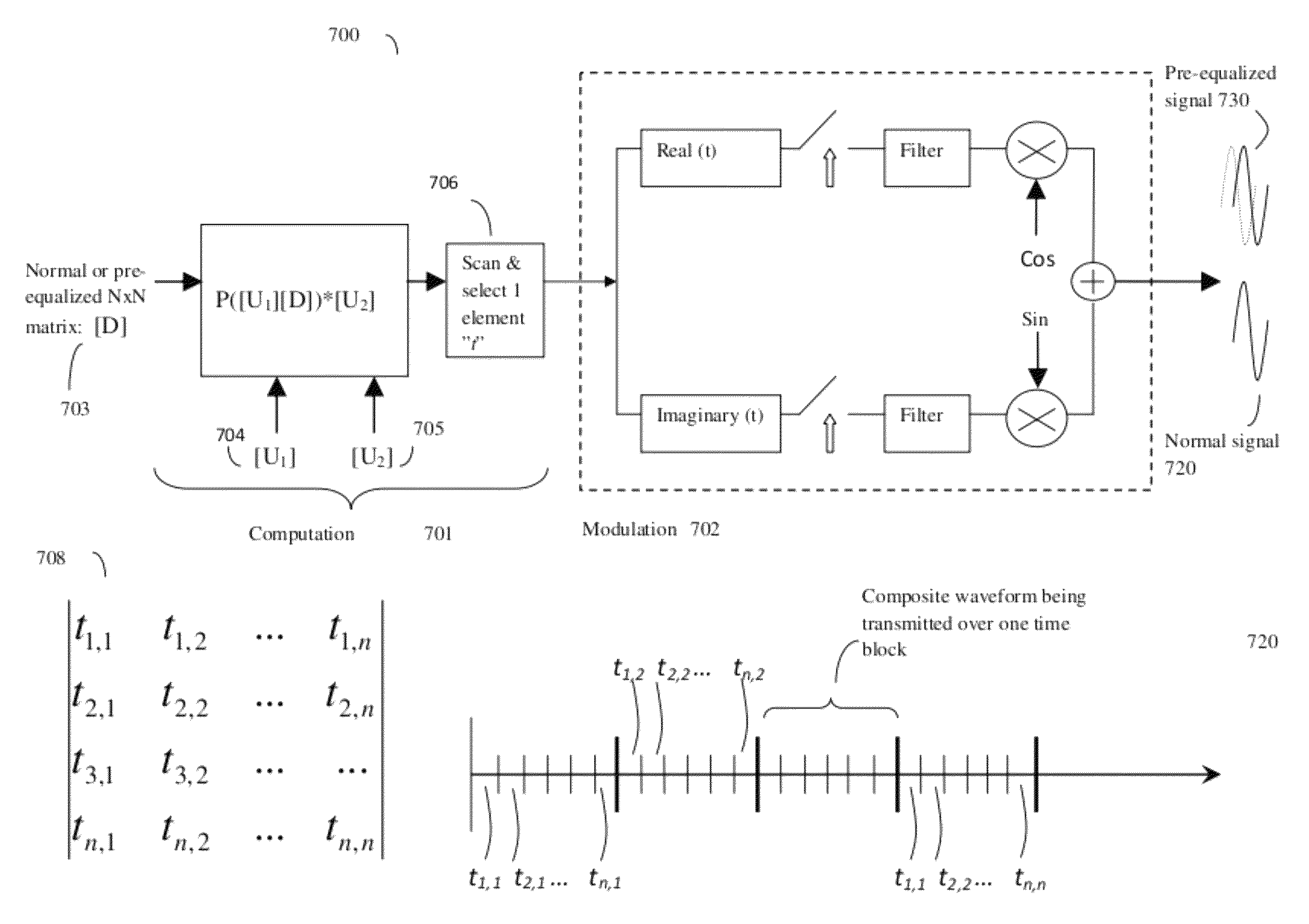
[0100]A microprocessor controlled transmitter may package a series of different symbols “d” (e.g. d1, d2, d3 . . . ) for transmission by repackaging or distributing the symbols into various elements of various N×N matrices [D] by, for example assigning d1 to the first row and first column of the [D] matrix (e.g. d1=d0,0), d2 to the first row second column of the [D] matrix (e.g. d2=d0,1) and so on until all N×N symbols of the [D] matrix are full. Here, once we run out of d symbols to transmit, the remaining [D] matrix elements can be set to be 0 or other value indicative of a null entry.

[0101]The various primary waveforms used as the primary basis for transmitting data, which here will be called “tones” to show that these waveforms have a characteristic sinusoid shape, can be described by an N×N Inverse Discrete Fourier Transform (IDFT) matrix [W], where for each element w in [W],

[0102]wj,k=ⅇⅈ⁢⁢2⁢⁢π⁢⁢j⁢⁢kN

or alternatively wj,k=eijθk or wj,k=[eiθk]j. Thus the individual data elements...


PUM


Abstract

A method of modulating communications signals, such as optical fiber, wired electronic, or wireless signals in a manner that facilitates automatic correction for the signal distortion effects of echoes and frequency shifts, while still allowing high rates of data transmission. Data symbols intended for transmission are distributed into N×N matrices, and used to weigh or modulate a family of cyclically time shifted and cyclically frequency shifted waveforms. Although these waveforms may then be distorted during transmission, their basic cyclic time and frequency repeating structure facilitates use of improved receivers with deconvolution devices that can utilize the repeating patterns to correct for these distortions. The various waveforms may be sent in N time blocks at various time spacing and frequency spacing combinations in a manner that can allow interleaving of blocks from different transmitters. Applications to channel sounding / characterization, system optimization, and also radar are also discussed.

Description

CROSS REFERENCE TO RELATED APPLICATIONS[0001]This application claims the priority benefit of provisional patent 61 / 615,884, “SIGNAL MODULATION METHOD RESISTANT TO ECHO REFLECTIONS AND FREQUENCY OFFSETS”, inventors Ronny Hadani and Shlomo Selim Rakib, filed Mar. 26, 2012; this application is also a continuation in part of U.S. patent application Ser. No. 13 / 117,119, ORTHONORMAL TIME-FREQUENCY SHIFTING AND SPECTRAL SHAPING COMMUNICATIONS METHOD, inventors Selim Shlomo Rakib and Ronny Hadani, filed May 26, 2011; Ser. No. 13 / 117,119 in turn claimed the priority benefit of US provisional application 61 / 349,619, “ORTHONORMAL TIME-FREQUENCY SHIFTING AND SPECTRAL SHAPING COMMUNICATIONS METHOD”, Inventors Selim Shlomo Rakib and Ronny Hadani, filed May 28, 2010; the contents of both applications are incorporated herein by reference.BACKGROUND OF THE INVENTION[0002]1. Field of the Invention[0003]The invention is in the general field of communications protocols and methods, and more specificall...

Claims


Application Information

Patent Timeline
Patent Type & Authority Patents(United States)
IPC IPC(8): H04L25/03H04L27/26H04L5/00H04W28/04H04W72/00H04W28/06
CPCH04L27/265H04L5/0016H04L27/2613H04L27/2634H04L27/2655H04L27/2697H04L25/03343H04W28/04H04W28/065H04W72/00H04L27/2639H04L27/26132
Inventor RAKIB, SHLOMO SELIMHADANI, RONNY
Owner COHERE TECH
Learn More