Engine mounting configuration for a turbofan gas turbine engine

a technology for gas turbine engines and mounting configurations, which is applied in the direction of machines/engines, manufacturing tools, transportation and packaging, etc., can solve the problems of increasing the clearance between static cases and rotating blade tips, affecting engine performance, and relative large “punch loads, so as to minimize backbone bending and engine case distortion

Active Publication Date: 2009-03-05
RAYTHEON TECH CORP
View PDF41 Cites 250 Cited by
  • Summary
  • Abstract
  • Description
  • Claims
  • Application Information

AI Technical Summary

Benefits of technology

[0009]The present invention therefore provides an engine mounting conf

Problems solved by technology

Although effective, one disadvantage of this mounting arrangement is the relatively large “punch loads” into the engine cases from the thrust links which react the thrust from the engine and couple the thrust to the pylon.
These loads tend to distort the intermediate case, low pressure compressor (LPC), fan, and high pressure compressor (H

Method used


Image

  • Engine mounting configuration for a turbofan gas turbine engine
  • Engine mounting configuration for a turbofan gas turbine engine
  • Engine mounting configuration for a turbofan gas turbine engine

Examples


Embodiment Construction

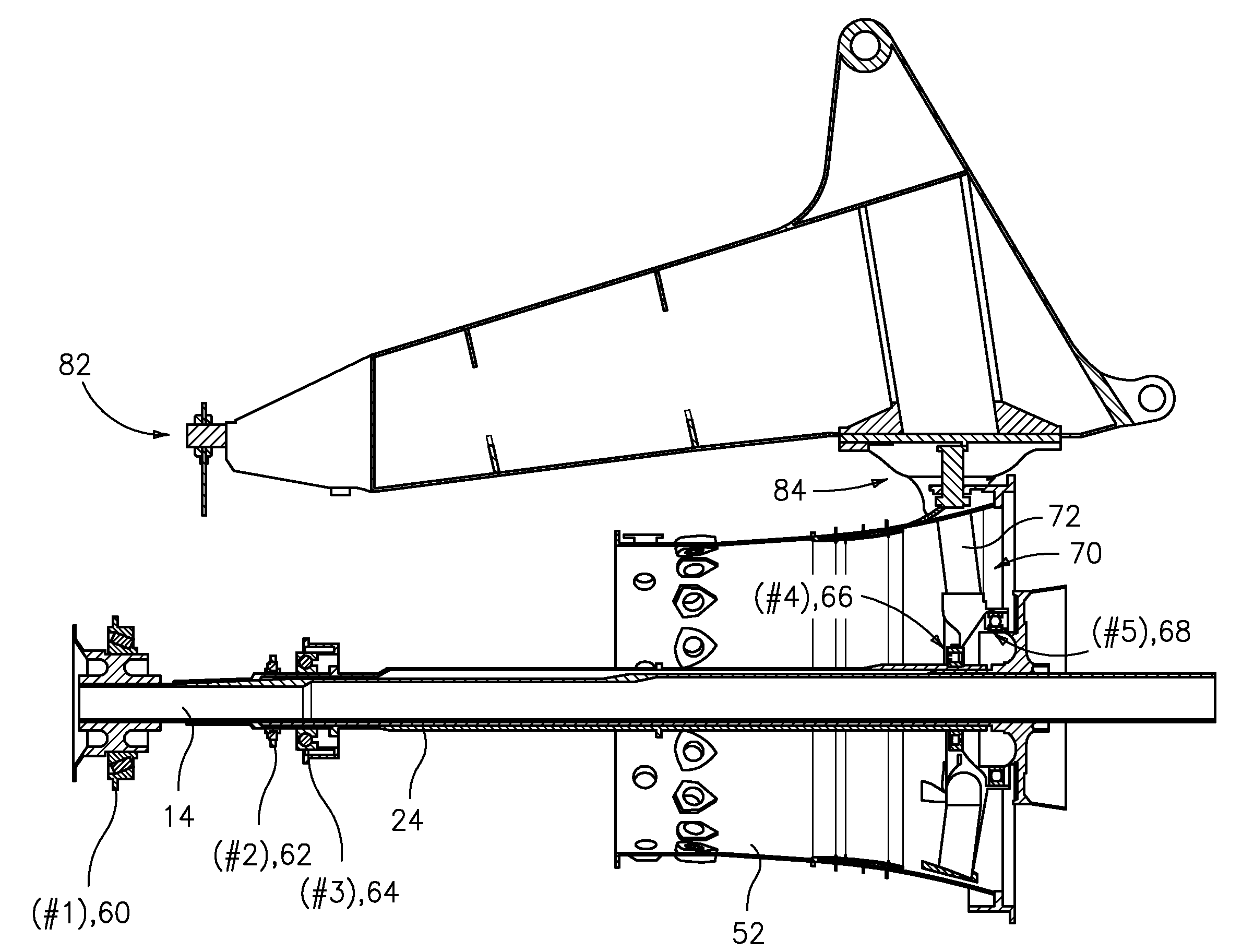
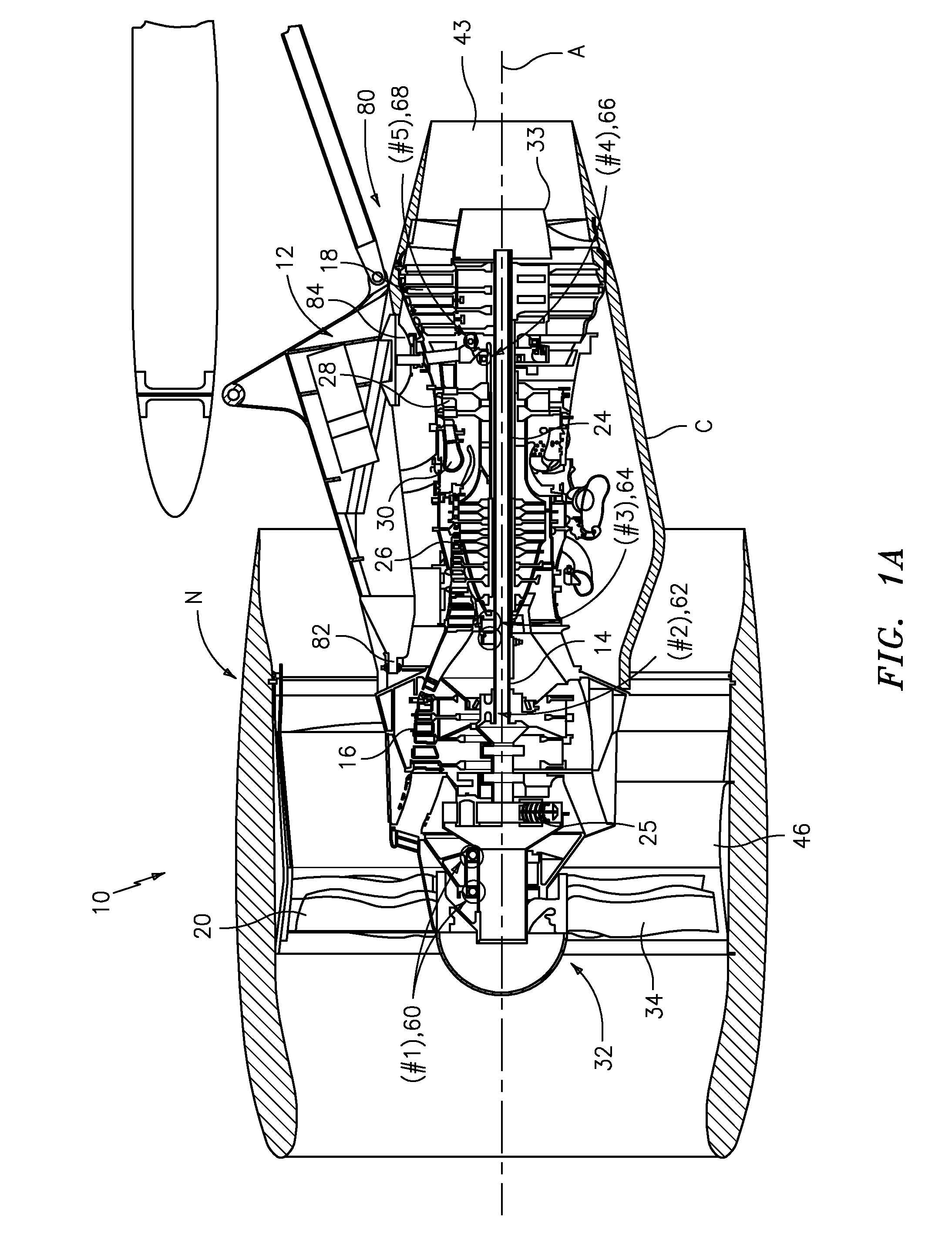
[0030]FIG. 1A illustrates a general partial fragmentary schematic view of a gas turbofan engine 10 suspended from an engine pylon 12 within an engine nacelle assembly N as is typical of an aircraft designed for subsonic operation.

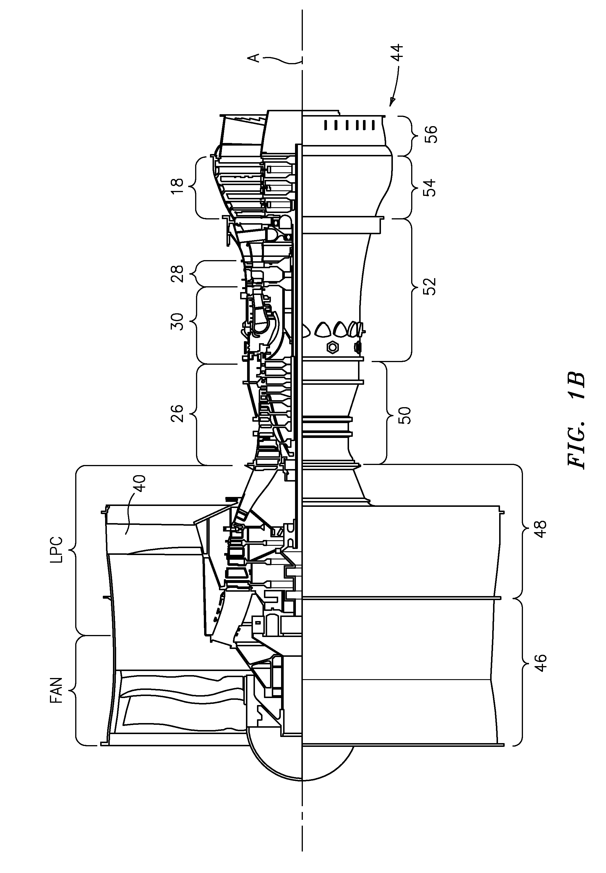
[0031]The turbofan engine 10 includes a core engine within a core nacelle C that houses a low spool 14 and high spool 24. The low spool 14 includes a low pressure compressor 16 and low pressure turbine 18. The low spool 14 drives a fan section 20 connected to the low spool 14 either directly or through a gear train 25.

[0032]The high spool 24 includes a high pressure compressor 26 and high pressure turbine 28. A combustor 30 is arranged between the high pressure compressor 26 and high pressure turbine 28. The low and high spools 14, 24 rotate about an engine axis of rotation A.

[0033]Airflow enters the fan nacelle N which at least partially surrounds the core nacelle C. The fan section 20 communicates airflow into the core nacelle C to the low pressure compre...


PUM


Abstract

An engine mounting configuration reacts engine thrust at an aft mount. The engine mounting configuration reduces backbone bending of the engine, intermediate case distortion and frees-up space within the core nacelle.

Description

BACKGROUND OF THE INVENTION[0001]The present invention relates to an engine mounting configuration, and more particularly to an engine mounting configuration for mounting a turbofan gas turbine engine to an aircraft pylon.[0002]A gas turbine engine may be mounted at various points on an aircraft such as a pylon integrated with an aircraft structure. An engine mounting configuration ensures the transmission of loads between the engine and the aircraft structure. The loads typically include the weight of the engine, its thrust, aerodynamic loads, maneuver loads, and rotary torque about the engine axis. The engine mounting configuration must also absorb the deformations to which the engine is subjected during different flight phases and the dimensional variations due to thermal expansion and retraction.[0003]One conventional engine mounting configuration includes a pylon having a forward mount and an aft mount. The front mount handles the thrust load from the engine as well as vertical...

Claims


Application Information

Patent Timeline
IPC IPC(8): F02C7/20B23P11/00
CPCF02C7/20B64D27/18Y10T29/49826B64D27/26Y02T50/44B64D2027/268Y02T50/40
Inventor SUCIU, GABRIEL L.MARX, JON A.MERRY, BRIAN D.NORDEEN, CRAIG A.DYE, CHRISTOPHER M.
Owner RAYTHEON TECH CORP
Why Eureka
Try Eureka