Multiple rotary knife for longitudinal splitting of webs

a technology of multi-rotary knives and webs, applied in metal working devices and other directions, can solve the problems of fast wear of cutting edges and considerable and costly complication in the production of knives, and achieve the effect of simple production and increased service li

Inactive Publication Date: 2016-01-05
TURMOND
View PDF15 Cites 3 Cited by
  • Summary
  • Abstract
  • Description
  • Claims
  • Application Information

AI Technical Summary

Benefits of technology

[0009]The object of the invention is to overcome the aforesaid drawbacks, and more in particular to provide a multiple rotary knife of the type defined above that will combine a considerably increased service life with ease and simplicity of production.

Problems solved by technology

This solution, albeit relatively inexpensive, entails in use the drawback of fast wear of the cutting edges and the consequent need for sharpening, which entails the need to remove and replace the multiple knife frequently, with the consequent pauses in operation of the cutting machine that derive therefrom.
This drawback is particularly critical in the case where the web undergoing splitting is of a high-friction material, for example a fibrous material or a material with adhesive surface.
If on the one hand this solution enables an appreciable increase in the service life of the knife, also reducing the need for periodic cleaning, it entails, however, a considerable and costly complication in the production of the knife in relation both to fixing of the hard-metal half-rings, which must be welded or bonded to the half-parts of the body, and to assemblage of said half-parts.

Method used


Image

  • Multiple rotary knife for longitudinal splitting of webs
  • Multiple rotary knife for longitudinal splitting of webs
  • Multiple rotary knife for longitudinal splitting of webs

Examples


first embodiment

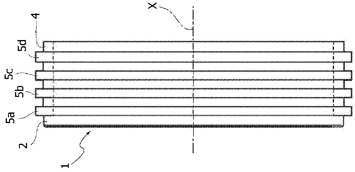
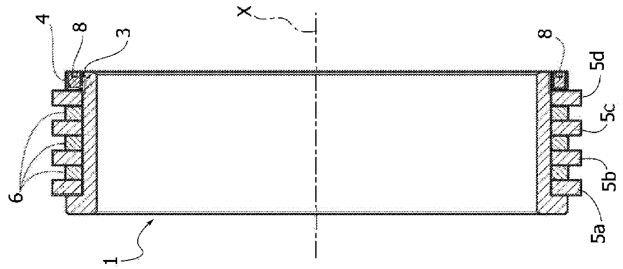
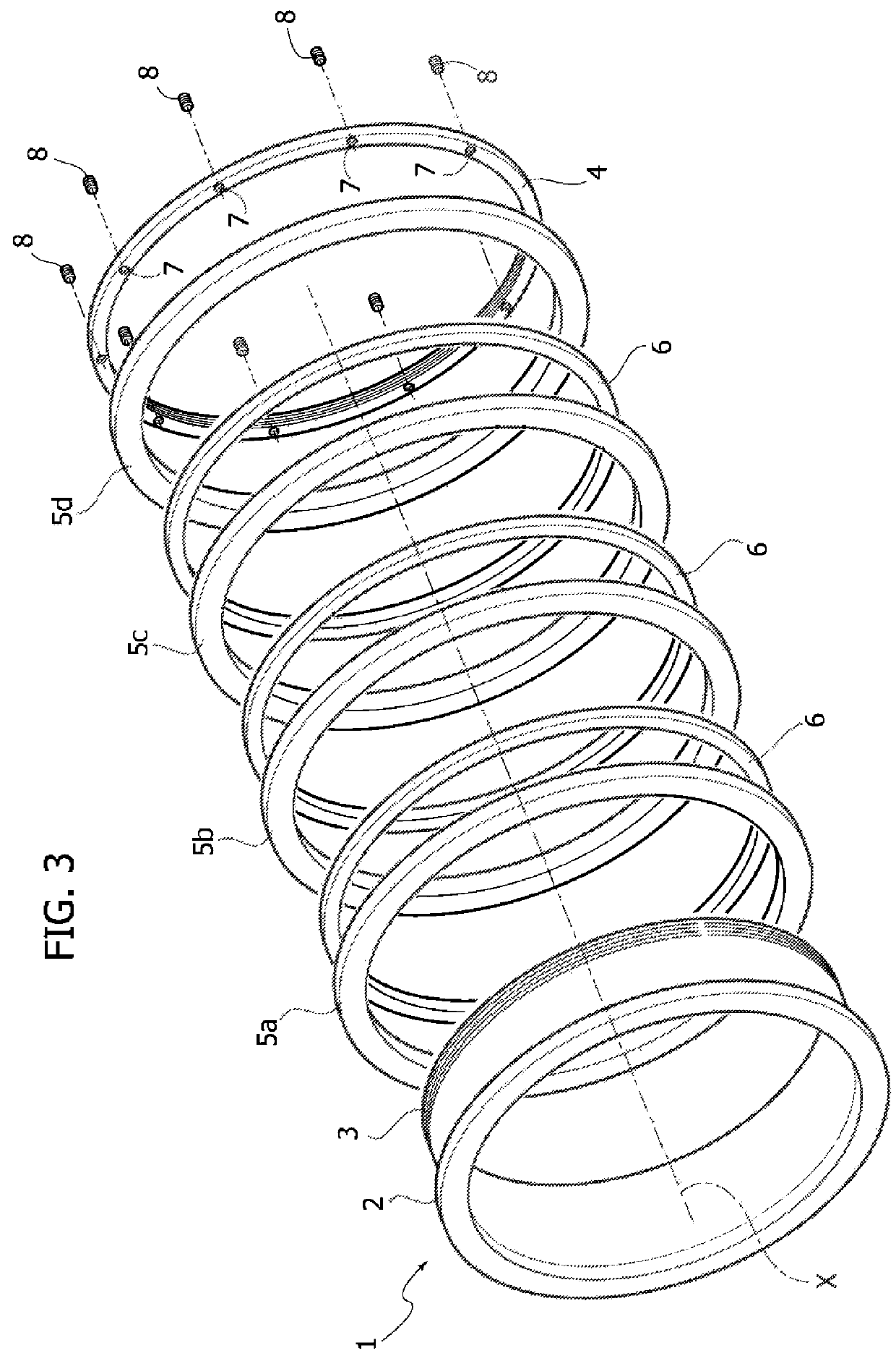
[0023]Illustrated in FIGS. 1 to 3 is the multiple rotary knife according to the invention that is currently considered preferred.

[0024]In a generally conventional way, the multiple knife is designed to be fixed on a rotating shaft of a machine for longitudinal splitting of webs so as to constitute a counterblade assembly, for example a bottom assembly, designed to co-operate with a top-blade assembly with reference to the path of advance of the web to be cut.

[0025]According to the preferred embodiment described herein, the multiple rotary knife comprises an annular body or hub 1 of a generally cylindrical shape and normally made of steel, having at one end an annular flange 2 and at the opposite end an external threaded 3, on which an internally threaded clamping ring 4 is screwed.

[0026]Between the flange 2 and the clamping ring 4 the hub 1 bears a plurality (in the example illustrated four in number) of circumferential blades 5a, 5b, 5c and 5d spaced apart, axially packed with the ...

second embodiment

[0031]The second embodiment illustrated in FIGS. 6 and 7 differs from the solution described previously in that the body of the multiple knife bearing the circumferential blades of hard metal is constituted, instead of by the hub described previously, by a set of annular elements 12 including a first end ring 13, a second end ring 14, and intermediate annular spacers 15. The hard-metal rings, in this case three in number 5a, 5b and 5c, are set between the end rings 13, 14 and the intermediate annular spacers 15 and are axially packed with these via a ring of axial screws 16 that traverse respective through holes 17 of the hard-metal rings 5a, 5b and 5c and holes 18 of the annular spacers 15, and the heads of which engage within respective seats 19 in the end ring 13. The opposite ends of the screws 16 are threaded and screwed into respective threaded holes 20 of the end ring 14.

[0032]The conformation of the cutting edges of the hard-metal rings 5a, 5b and 5c is altogether identical ...


PUM

PropertyMeasurementUnit
angleaaaaaaaaaa
angleaaaaaaaaaa
angleaaaaaaaaaa

Abstract

A multiple rotary knife for longitudinal splitting of webs, includes a generally cylindrical annular body bearing a plurality of circumferential blades spaced apart. The circumferential blades are formed by continuous hard-metal rings mechanically fixed axially to the annular body.

Description

CROSS-REFERENCE TO RELATED APPLICATIONS[0001]This application claims priority to Italian Patent Application No. TO2012A000346 filed on Apr. 18, 2012, the entire disclosure of which is incorporated herein by reference.FIELD OF THE INVENTION[0002]The present invention relates in general to splitting of continuous webs into longitudinal strips, with particular, albeit non-exclusive, reference to the production of adhesive tape, medical plasters and the like, with the use of equipment that employs a pair of multiple rotary knives between which the longitudinal web to be cut is fed in a direction perpendicular to the axes of rotation of the rotary knives.[0003]More in particular, the invention regards the aforesaid multiple rotary knives, and even more in particular to the bottom knife that operates like a multiple counterblade with the top knife of cutting equipment of the above sort.PRIOR ART[0004]The multiple rotary knife that forms the subject of the invention conventionally consists...

Claims


Application Information

Patent Timeline
Patent Type & Authority Patents(United States)
IPC IPC(8): B26D1/143B26D1/00B26D1/24
CPCB26D1/1435B26D1/0006B26D1/245B26D2001/006B26D2001/0033Y10T83/9374
Inventor COLOMBATTO, ALESSANDRO
Owner TURMOND
Why Eureka
Try Eureka