Craniosynostosis detection system

Active Publication Date: 2016-01-12
ASFORA IP
View PDF6 Cites 0 Cited by
  • Summary
  • Abstract
  • Description
  • Claims
  • Application Information

AI Technical Summary

Benefits of technology

This patent describes a new system for detecting craniosynostosis, a condition that causes premature closure of the skull. The new system is designed to be simple and non-invasive, making it easier to diagnose. Its goal is to improve the accuracy and efficiency of craniosynostosis detection.

Problems solved by technology

The premature closure of the sutures in craniosynostosis may result in increased intracranial pressure and skull deformity, which may have a detrimental effect on the development of an infant's brain as the brain is unnaturally constricted.
Unfortunately, the craniosynostosis condition is often not detected until after the sutures of the skull bones have fully fused and there is an obvious skull deformity.
The remedies for the condition at this point are more complicated.
However, this is not a reliable indicator because even if there is a noticeable change in the shape of the infant's head, the misshapen head may simply be the result of the effects of labor and delivery on the soft unfused skull, or exposure of the unfused skull to long periods of pressure applied to the infant's head while lying in the same position; the so-called plagiocephaly.
Moreover, there are few if any simple and reliable ways of diagnosing the early craniosynostosis condition before significant skull deformity, or discriminating between it and the less serious positional plagiocephaly, particularly in the clinical setting.
Also, in the early stages in which the suture is partially open or fused at a very small segment, false negatives are high.

Method used


Image

  • Craniosynostosis detection system
  • Craniosynostosis detection system
  • Craniosynostosis detection system

Examples


Embodiment Construction

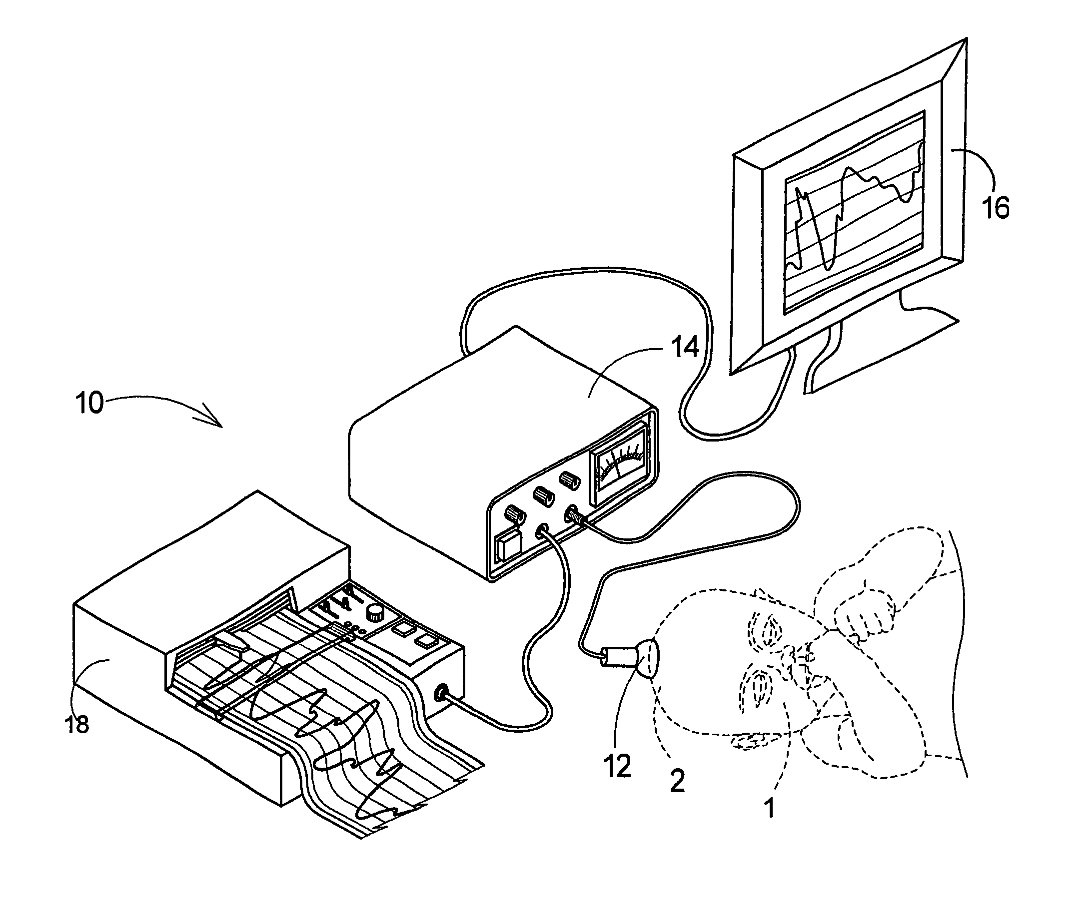
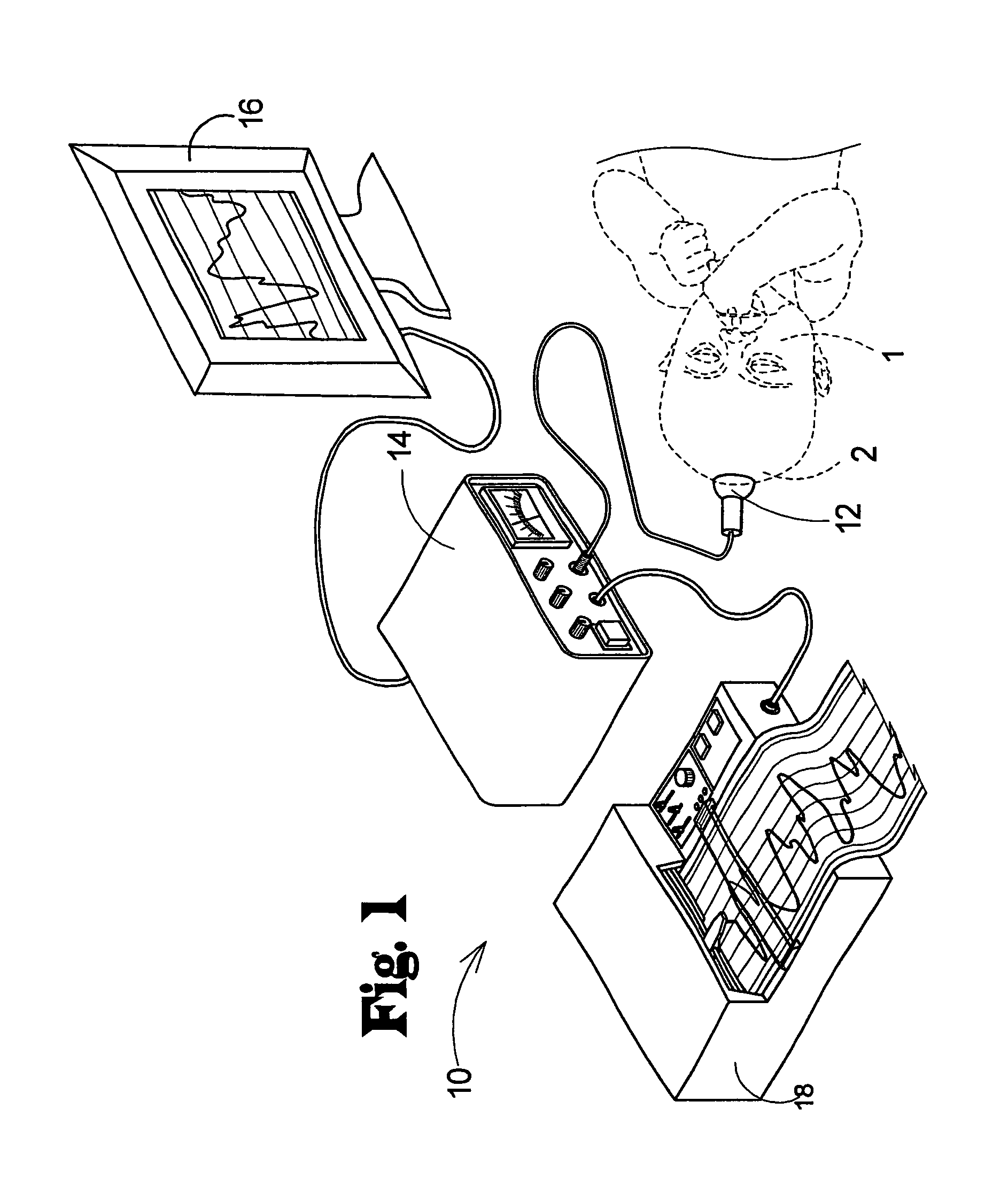
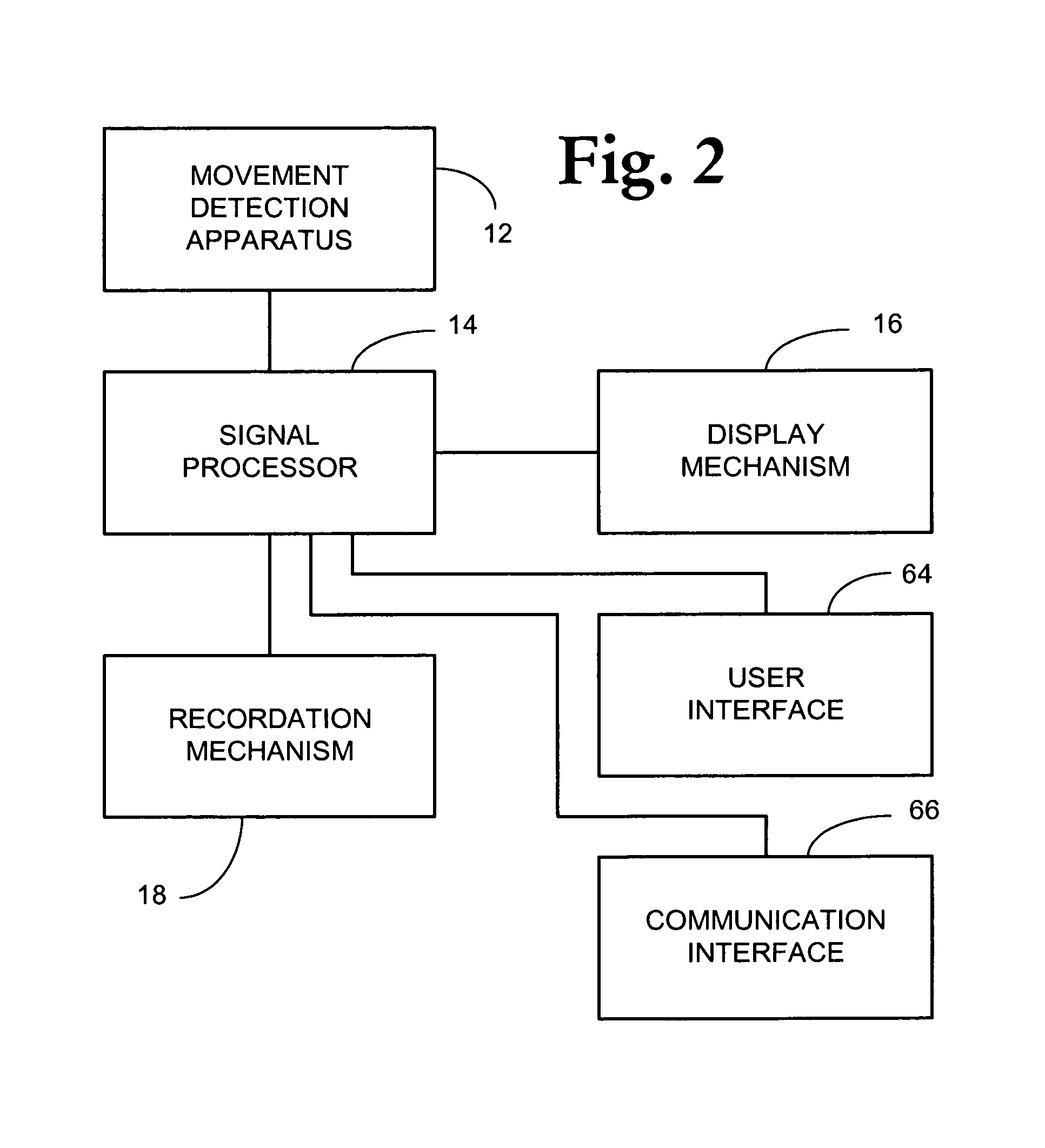
[0026]With reference now to the drawings, and in particular to FIGS. 1 through 10 thereof, a new craniosynostosis detection system embodying the principles and concepts of the disclosed subject matter will be described.

[0027]As a matter of background and clarity for the following description, and referring to FIGS. 3 and 4, the head 1 of the infant patient has a skull 2 formed of a plurality of relatively flat bones 4 with sutures 5 therebetween. The sutures 5 are characterized by gaps in which fibrous connective tissue 6 is located and joins the spaced bones 4. The fibrous connective tissue 6 extends along the sutures 5 between the bones 4. The brain 7 of the patient is located on the skull 2. The scalp 8 of the patient's head overlies the bones 4 of the skull 2 as well as the fibrous connective tissue 6 in the sutures 5. The scalp 8 has an outer surface 9, and the patient may have hair extending from the outer surface 9.

[0028]The craniosynostosis detection system 10 may comprise a...


PUM


Abstract

A craniosynostosis detection system is disclosed that may comprise a movement detection apparatus configured to detect movement in a surface of the scalp of the patient along areas between bones of the skull when at least a portion of the movement detection apparatus is positioned adjacent to the surface of the scalp. The movement detection apparatus may generate a signal corresponding to movement detected by the movement detection apparatus. A signal processing apparatus may be operatively connected to the movement detection apparatus and configured to receive the movement signal from the movement detection apparatus. A data display apparatus may be operatively connected to the signal processing apparatus and configured to display a representation of movement detected by the movement detection apparatus. The absence of movement of the scalp over the sutures, which correspond to the brain pulsations, is diagnostic of craniosynostosis.

Description

BACKGROUND[0001]1. Field[0002]The present invention relates to the early detection of craniosynostosis in neonates and infants, utilizing a simple, noninvasive and very rapid diagnostic method without the use of x-ray technology, and even before any skull deformity is noticeable.[0003]2. Description of the Prior Art[0004]For a period of time after birth, the sutures between the flat bones of the skull of an infant remain open and unfused to permit brain and skull growth. The flat bones are separated by areas of dense connective tissue which are fibrous and moveable which are needed for the ongoing growth. The areas of connective tissue are eventually ossified into bone. However, while the posterior areas of connective tissue between the bones may close by eight weeks after birth, the anterior rears of connective tissue may remain up to eighteen months after birth before the ossification occurs. Thus, the time periods for such ossification may vary greatly.[0005]Craniosynostosis is a...

Claims


Application Information

Patent Timeline
IPC IPC(8): A61B5/103A61B5/00A61B5/11A61B5/113
CPCA61B5/113A61B5/4504A61B5/11A61B2503/04A61B2503/045A61B5/6814
Inventor ASFORA, WILSON, T.
Owner ASFORA IP
Why Eureka
Try Eureka