

Property modulated materials and methods of making the same
a technology of property modulation and materials, applied in the field of layers, can solve the problems of preventing or limiting the use of composite materials in some applications, material failure may be due, etc., and achieve the effects of preventing defect or crack propagation, and reducing the possibility of crack formation or stress pile-up
- Summary
- Abstract
- Description
- Claims
- Application Information
AI Technical Summary
Benefits of technology
Problems solved by technology
Method used
Image

Examples
examples
[0062]The following examples are merely intended to illustrate the practice and advantages of specific embodiments of the present disclosure; in no event are they to be used to restrict the scope of the generic disclosure.
example i
Temperature Modulation
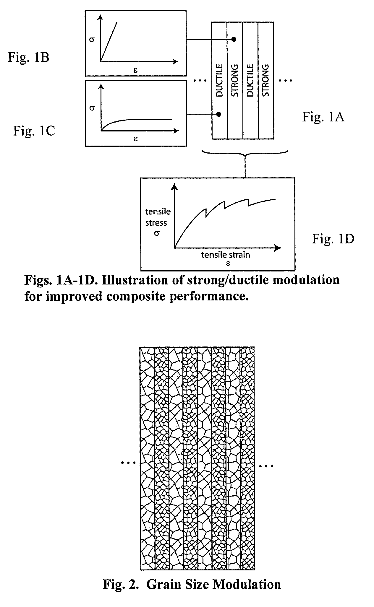
[0063]One-dimensionally modulated (laminated) materials can be created by controlled, time-varying electrodeposition conditions, such as, for example, current / potential, mass transfer / mixing, or temperature, pressure, and, electrolyte composition. An example for producing a laminated, grain-size-modulated material is as follows:
1. Prepare an electrolyte consisting of 1.24 M FeCl2 in deionized water.
2. Adjust the pH of the electrolyte to −0.5-1.5 by addition of HCl.
3. Heat the bath to 95° C. under continuous carbon filtration at a flow rate of ˜2-3 turns (bath volumes) per minute.
4. Immerse a titanium cathode and low-carbon steel anode into the bath and apply a current such that the plating current on the cathode is at least 100 mA / cm2.
5. Raise and lower the temperature of the bath, between 95° C. (large grains) and 80° C. (smaller grains) at the desired frequency, depending on the desired wavelength of grain size modulation. Continue until the desired thickness...
example ii
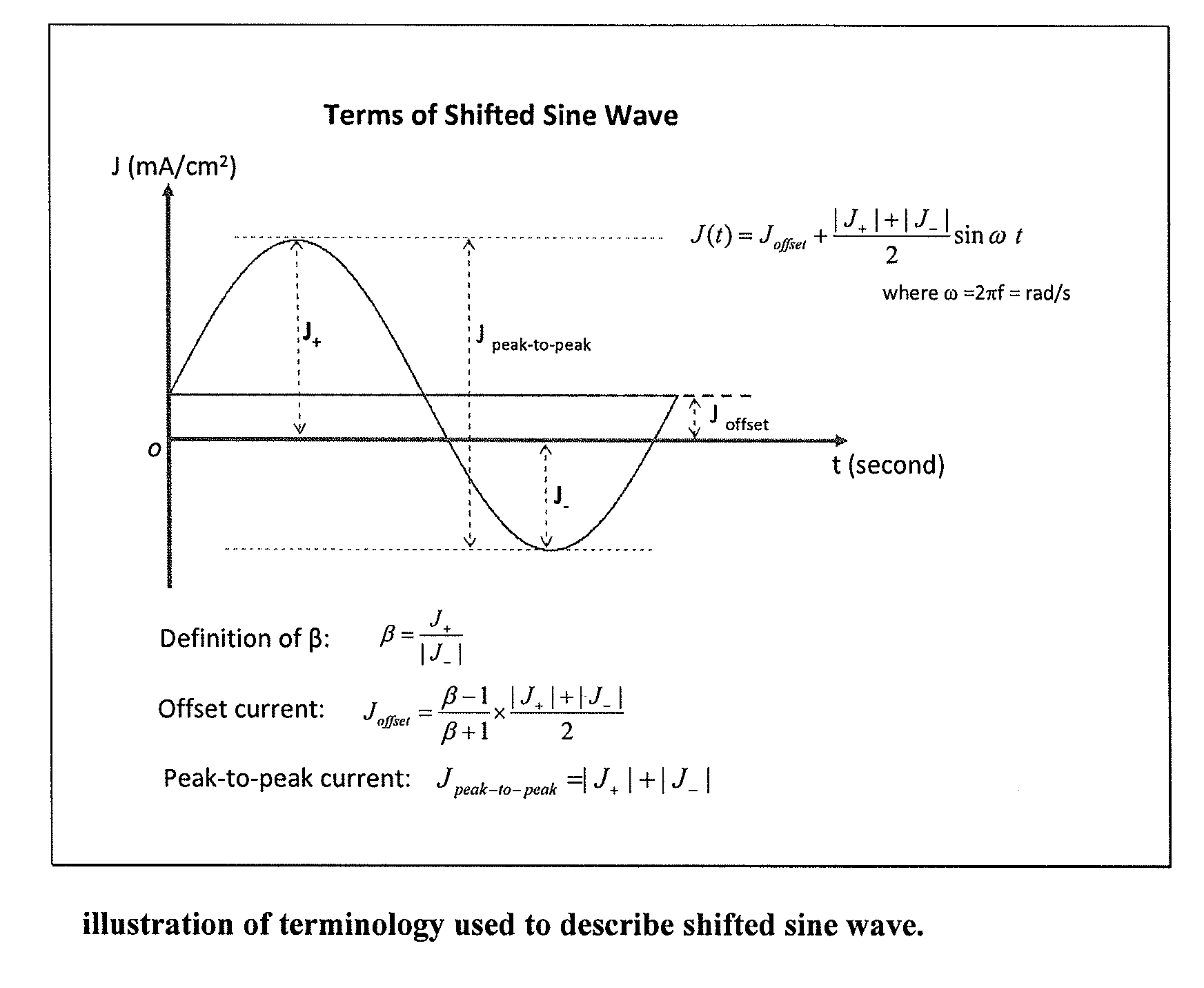
Beta Modulation
[0064]This example involves electroplating NMCs by modulating the beta value. In embodiments where the current density is applied as a sine wave having (1) a peak cathodic current density value (J+>0), (2) a peak anodic current density value (J−1.5), the plated iron layers have high hardness and low ductility. The laminated structure with modulated hardness and ductility makes the material stronger than homogeneous material.
[0065]The electroplating system includes a tank, electrolyte of FeCl2 bath with or without CaCl2, computer controlled heater to maintain bath temperature, a power supply, and a controlling computer. The anode is low carbon steel sheet, and cathode is titanium plate which will make it easy for the deposit to be peeled off. Carbon steel can also be used as the cathode if the deposit does not need to be peeled off from the substrate. Polypropylene balls are used to cover the bath surface in order to reduce bath evaporation.
[0066]The process for produc...
PUM
| Property | Measurement | Unit |
|---|---|---|
| peak current density | aaaaa | aaaaa |
| peak current density | aaaaa | aaaaa |
| peak current density | aaaaa | aaaaa |
Abstract
Description
Claims
Application Information