Elastomeric tire for a tracked vehicle

a technology of elastomeric tires and tracked vehicles, which is applied in the field of non-pneumatic tires, can solve the problems of rubber tires blowing out and heat checking at high operating temperatures, affecting the service life of rubber tires, so as to prolong the useful life of tire assemblies and reduce the frequency of tire replacement. the effect of the frequency of replacemen

Active Publication Date: 2012-06-14
GSE TECH
View PDF13 Cites 6 Cited by
  • Summary
  • Abstract
  • Description
  • Claims
  • Application Information

AI Technical Summary

Benefits of technology

[0010]In one embodiment, a tire assembly for a tracked vehicle has an inner tire layer forming a first tube sized to substantially cover an outer surface of a rim of a wheel, and an outer tire layer forming a second tube with a larger diameter than the first tube, the outer tire layer adapted to contact a track of a vehicle. At least one carcass layer is interposed between the inner and outer tire layers to provide tensile and impact strength to prevent crack propagation from reaching the inner tire layer of the tire assembly, thereby prolonging the useful life of the tire assembly and reducing the frequency of replacement of the tire assembly. The inner and outer tire layers encapsulate the carcass layer to protect it from an environment of use.
[0011]In another embodiment a wheel assembly for a tracked vehicle has a wheel with a circular mounting flange with a wall extending radially outwards and circumferentially therefrom, and a peripheral rim connected to an outer edge of the wall. The peripheral rim has an outer surface. The wheel assembly also has a tire with an inner layer sized to substantially cover the outer surface of the peripheral rim, at least one intermediate fabric carcass layer bonded to an outer surface of the inner layer, and an outer layer bonded to an outer surface of the at least one carcass layer. The outer layer is adapted to contact a track of a vehicle. The at least one intermediate carcass layer provides tensile and impact strength to prevent crack propagation from reaching the inner layer of the tire, thereby prolonging the useful life of the tire and reducing the frequency of replacement of the tire.
[0012]Yet another embodiment provides a method of forming a tire assembly for a wheel of a tracked vehicle. An inner tire layer is provided as a first tube about a rim of a wheel. The inner tire layer is sized to substantially cover an outer surface of the rim. An outer tire layer is positioned about the inner tire layer as a second tube with a larger diameter than the first tube. The outer tire layer is adapted to contact a track of a vehicle. At least one carcass layer is interposed between the inner and outer tire layers. The carcass layer provides tensile and impact strength to prevent crack propagation from reaching the inner tire layer of the tire assembly, thereby prolonging the useful life of the tire assembly and reducing the frequency of replacement of the tire assembly. The inner and outer tire layers encapsulate the carcass layer to protect it from an environment of use.

Problems solved by technology

Typical failure modes of these rubber tires are blow-out and heat checking from high operating temperatures, cutting and chunking from sharp debris, and bonding failure at the rubber-wheel interface.
Failure of the elastomer rubber tire on the road wheel may account for more than ninety-five percent of all road wheel failures.
Once the elastomer tensile forces at the tip of the debris exceed the tensile strength of the elastomer, a crack initiates and then begins to propagate.
Unfortunately, the tensile strength of elastomer decreases drastically with higher operating temperatures over 175 F or 200 F. The higher temperatures promote crack initiation by weakening the tire.
The cutting and chunking characteristics may be improved with polyurethane, but drawbacks include a lower operating temperature threshold, a harder ride with increased vibrations, additional cost, and greater susceptibility to contaminants and humidity during adhesion molding.

Method used


Image

  • Elastomeric tire for a tracked vehicle
  • Elastomeric tire for a tracked vehicle
  • Elastomeric tire for a tracked vehicle

Examples


Embodiment Construction

[0025]As required, detailed embodiments of the present invention are disclosed herein; however, it is to be understood that the disclosed embodiments are merely exemplary of the invention that may be embodied in various and alternative forms. The figures are not necessarily to scale; some features may be exaggerated or minimized to show details of particular components. Therefore, specific structural and functional details disclosed herein are not to be interpreted as limiting, but merely as a representative basis for the claims and / or as a representative basis for teaching one skilled in the art to variously employ the present invention.

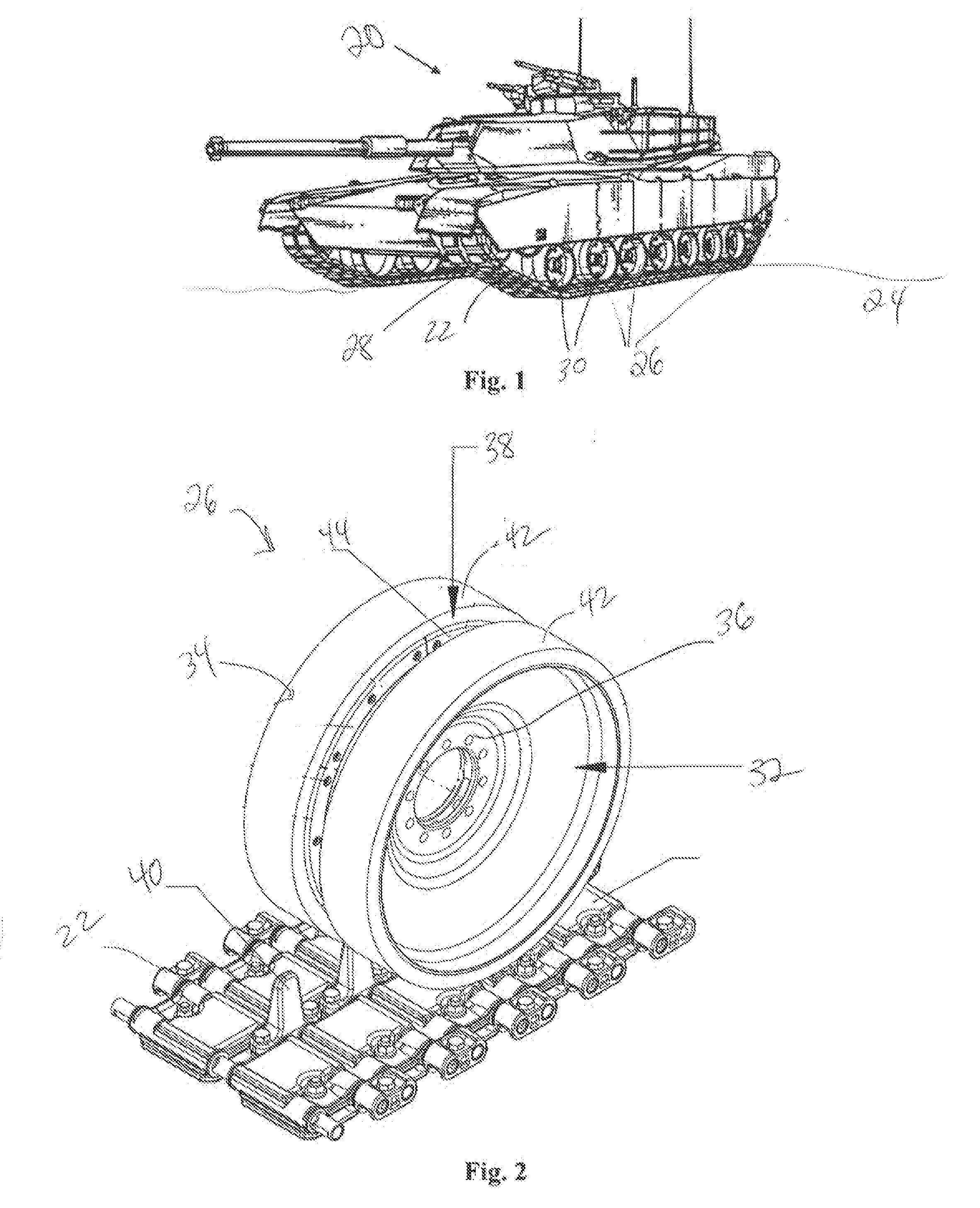
[0026]FIG. 1 illustrates a tracked vehicle 20. The tracked vehicle 20 may be an armored tank as shown, and may also be any military, commercial, or other tracked vehicle as is known in the art. The vehicle 20 has a track 22 to interact with an underlying surface 24. The underlying surface may be a road, or uneven terrain such as dirt, rock, or the l...


PUM

PropertyMeasurementUnit
diameteraaaaaaaaaa
tensileaaaaaaaaaa
impact strengthaaaaaaaaaa

Abstract

A road wheel for a tracked vehicle is provided with a circular mounting flange having a dished wall extending radially outwards and circumferentially therefrom, a peripheral rim having a first edge and a second edge with the rim connected to an outer edge of the dished wall at an intermediate region of the rim, and a first lip extending from the first edge. Another road wheel for a tracked vehicle is provided with a mounting flange, a peripheral rim, at least one inner dished wall, at least one outer dished wall offset from the inner dished wall along the flange, and at least two connector walls with each connector wall extending between the inner dished wall, outer dished wall, and the peripheral rim.

Description

[0001]The invention was made in part with Government support. The Government may have certain rights to the invention.BACKGROUND[0002]1. Technical Field[0003]The invention relates to non-pneumatic tires for use with tracked vehicles.[0004]2. Background Art[0005]Tracked vehicles have applications in military use, heavy commercial use, and others where the vehicle may be travelling over uneven terrain, carrying a heavy load, or the like. The vehicles have a track which interfaces with the ground to support or propel the vehicle. Wheels are located within the track to drive or support it. Some of the wheels are connected to the drivetrain of the vehicle. A tire is placed over the rim of the wheels to interface with the track to improve ride quality characteristics. The tires are typically made from a natural or synthetic rubber and are solid, or non-pneumatic.[0006]Typical failure modes of these rubber tires are blow-out and heat checking from high operating temperatures, cutting and c...

Claims


Application Information

Patent Timeline
Patent Type & Authority Applications(United States)
IPC IPC(8): B62D55/14B23P11/00B60C7/08
CPCB60C7/102B62D55/0966Y10T152/10306Y10T29/49494B62D55/145
Inventor SIMULA, GLEN RAYMOND
Owner GSE TECH
Why Eureka
Try Eureka