Radiation imaging apparatus, method of controlling the same, and radiation imaging system

a radiation imaging and control method technology, applied in the direction of radiation controlled devices, instruments, optical radiation measurement, etc., can solve the problem of not being able to determine the radiation irradiation with sufficient accuracy, and achieve the effect of improving the determination accuracy and sufficient accuracy

Active Publication Date: 2016-01-12
CANON KK
View PDF25 Cites 33 Cited by
  • Summary
  • Abstract
  • Description
  • Claims
  • Application Information

AI Technical Summary

Benefits of technology

[0005]The radiation imaging apparatus disclosed in the above literature performs a subtraction process by using the current value obtained in advance by tests at factory shipment or the like. However, the current flowing in each bias line depends on the state of the radiation imaging apparatus when it measures the current. For example, the current value based on the dark charge flowing in the bias line can vary in a test at factory shipment and at the time of actual use. For this reason, it is not possible to determine the irradiation of radiation with sufficient accuracy even when correcting the current flowing in the bias line by using the current value obtained in advance by tests. An aspect of the present invention provides a technique of improving the accuracy of determination on whether radiation is irradiated onto a radiation imaging apparatus.

Problems solved by technology

For this reason, it is not possible to determine the irradiation of radiation with sufficient accuracy even when correcting the current flowing in the bias line by using the current value obtained in advance by tests.

Method used


Image

  • Radiation imaging apparatus, method of controlling the same, and radiation imaging system
  • Radiation imaging apparatus, method of controlling the same, and radiation imaging system
  • Radiation imaging apparatus, method of controlling the same, and radiation imaging system

Examples


Embodiment Construction

[0019]The embodiments will be described below with reference to the accompanying drawings. The same reference numerals denote the same elements throughout various embodiments, and a repetitive description of them will be omitted. In addition, the respective elements can be changed and combined as needed.

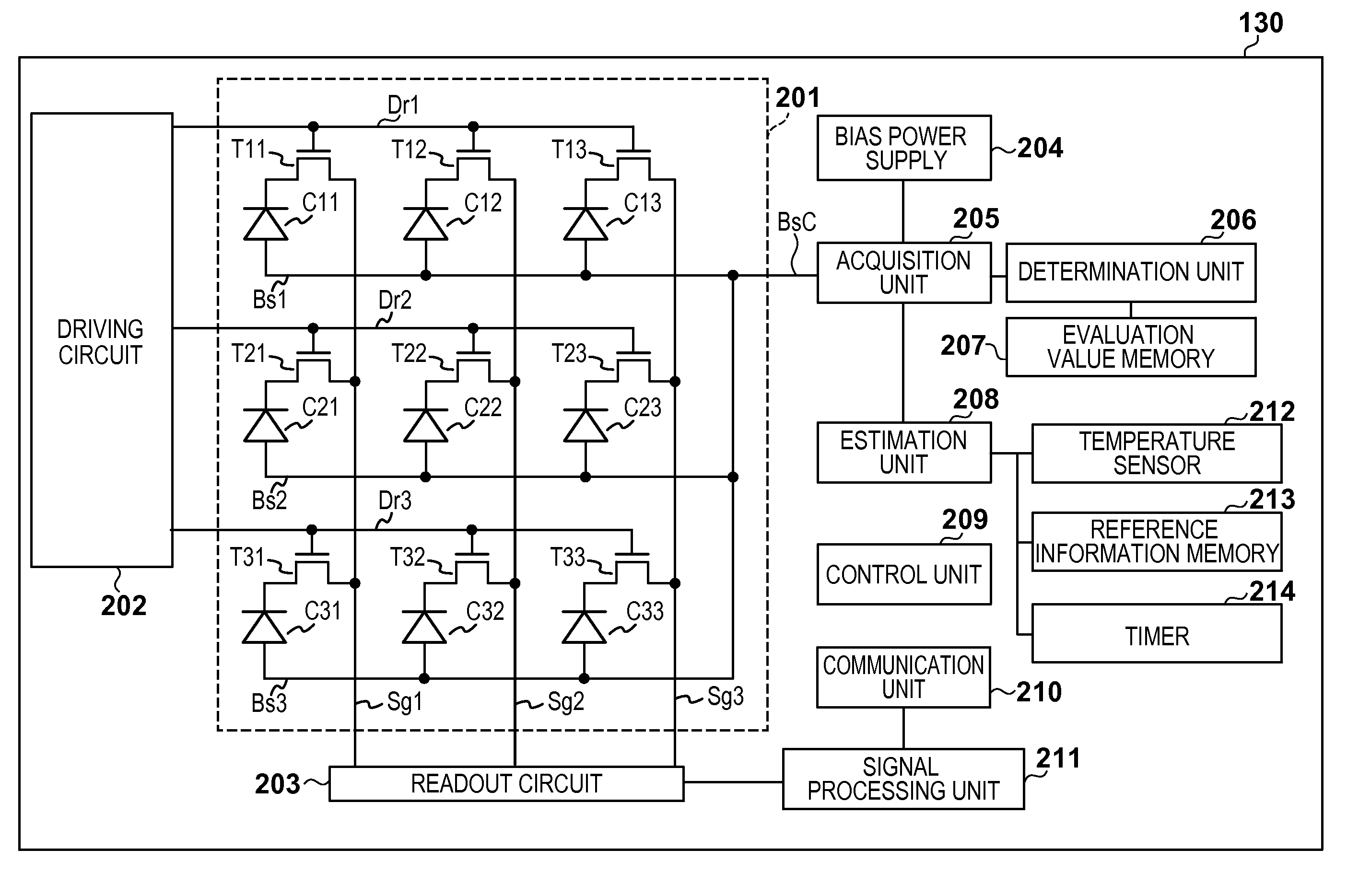
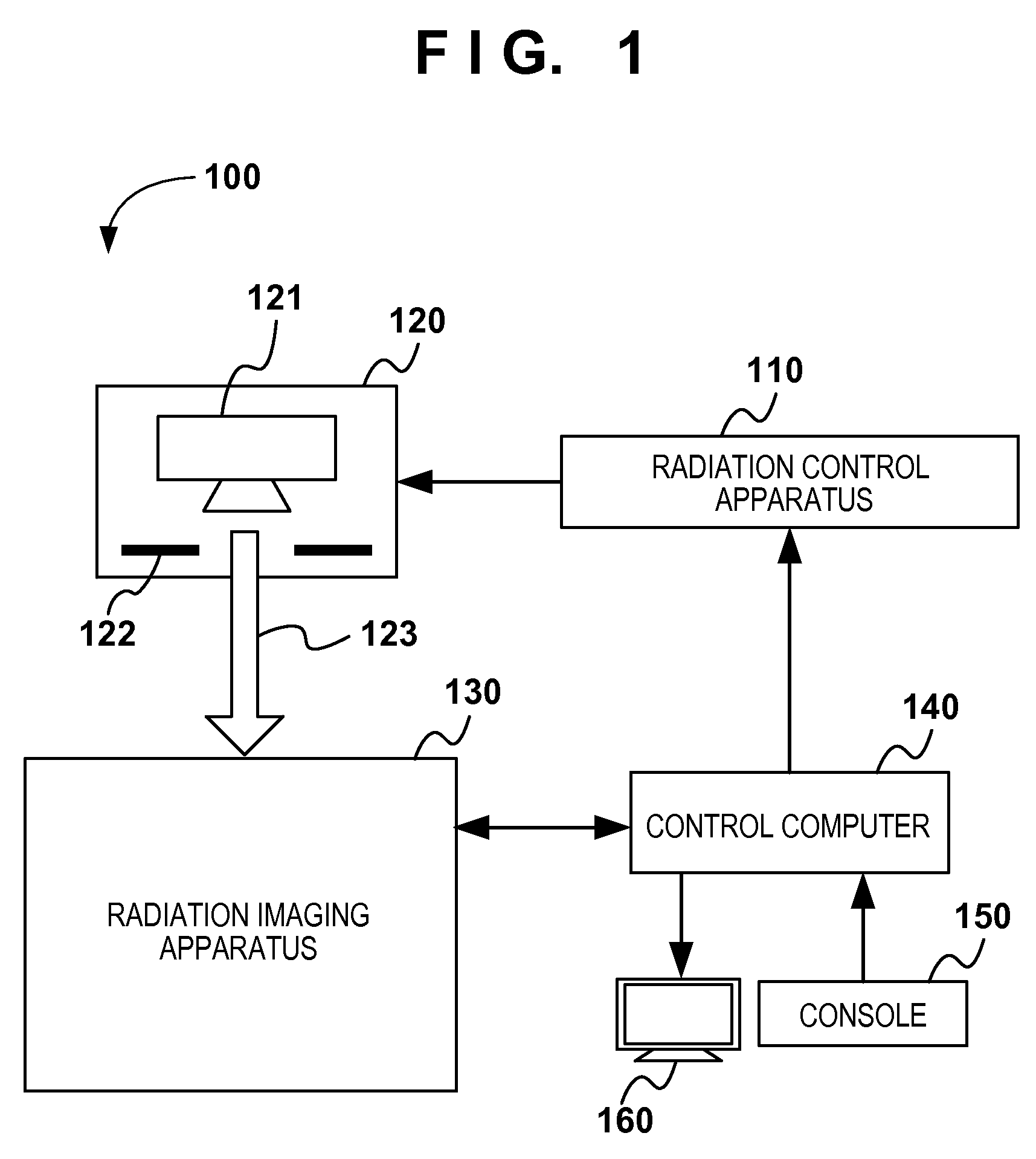
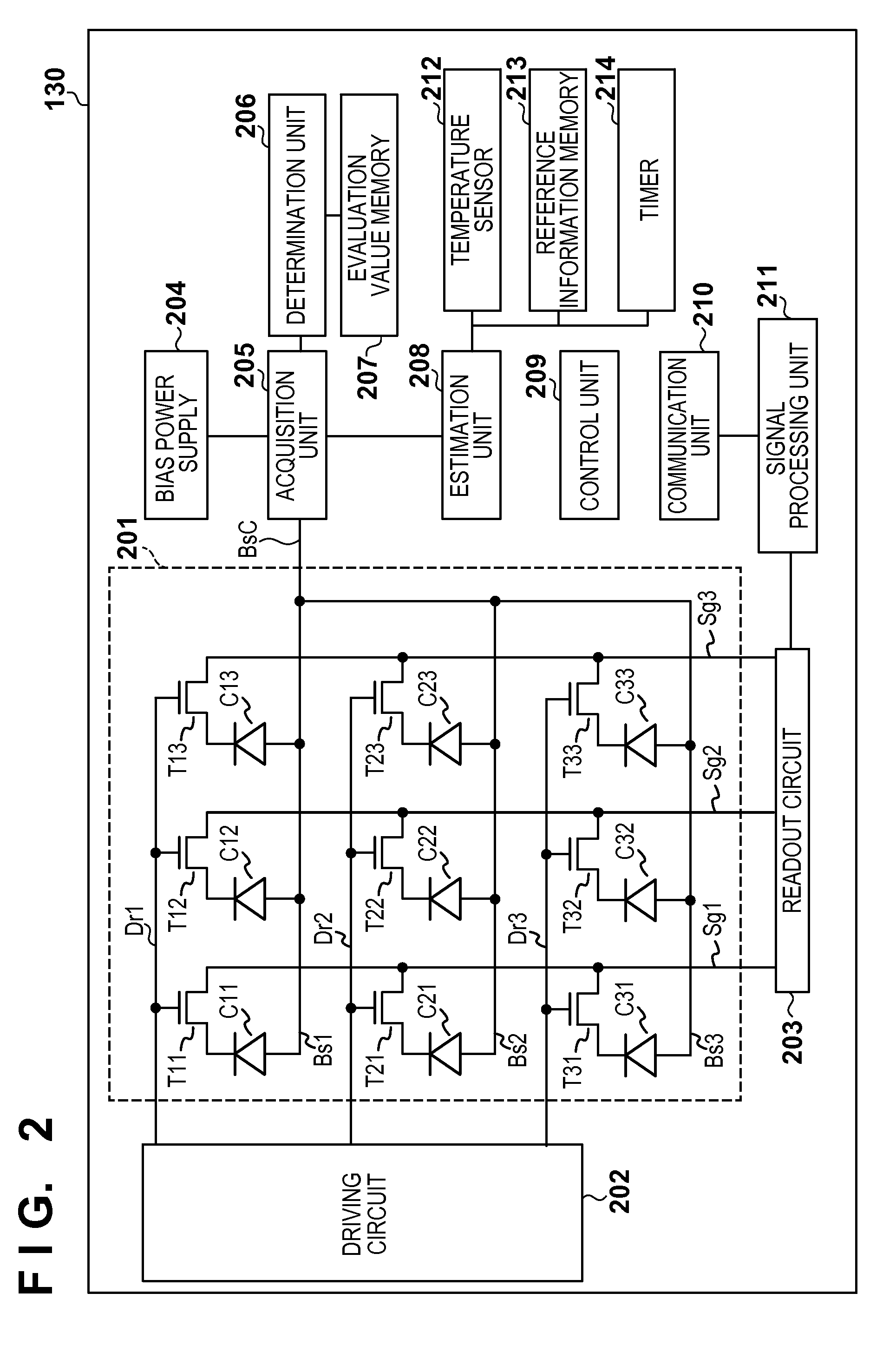
[0020]An example of the arrangement of a radiation imaging system 100 according to various embodiments will be described first with reference to FIG. 1. The radiation imaging system 100 is used for still image capturing such as general imaging and moving image capturing such as fluoroscopy in, for example, medical diagnosis. The radiation imaging system 100 can include a radiation control apparatus 110, a radiation generating apparatus 120, a radiation imaging apparatus 130, a control computer 140, a console 150, and a display device 160.

[0021]The radiation control apparatus 110 controls the operations of a radiation source 121 and an exposure field aperture mechanism 122 which are i...


PUM


Abstract

A radiation imaging apparatus including pixels; driving lines; a driving circuit; bias lines; an acquisition unit configured to acquire an evaluation value based on a current flowing in the bias line; a determination unit configured to compare the evaluation value with a comparison target value to determine whether radiation is irradiated; a control unit configured to control the acquisition unit and the determination unit; and a storage unit configured to store the evaluation value used in the determination process, is provided. A comparison target value used in a given determination process is based on one or more evaluation values used in one or more determination processes which are performed before the given determination process and in which it is determined that radiation has not been irradiated.

Description

BACKGROUND OF THE INVENTION[0001]1. Field of the Invention[0002]The present invention relates to a radiation imaging apparatus, a method of controlling the same, and a radiation imaging system.[0003]2. Description of the Related Art[0004]Recently, medical imaging diagnosis and nondestructive inspection with radiation such as X-rays have been performed by using a radiation imaging apparatus which can output digital images. Japanese Patent Laid-Open No. 2010-268171 proposes a radiation imaging apparatus which automatically determines whether radiation is irradiated from a radiation generating apparatus. This radiation imaging apparatus includes a plurality of pixels. Each pixel includes a conversion element which converts X-rays or light into charge and a switching element which can apply a desired voltage to one of the electrodes of the conversion element. A bias voltage is applied to the other electrode of the conversion element via a bias line. When radiation is irradiated onto the...

Claims


Application Information

Patent Timeline
Patent Type & Authority Patents(United States)
IPC IPC(8): G01T1/00A61B6/00H01L27/146H04N5/376H04N5/32G01T1/16
CPCG01T1/16A61B6/4233H01L27/14658H04N5/32H04N5/376A61B6/00A61B6/42A61B6/44A61B6/5205A61B6/58G01N23/00G01N23/04G01N23/043H04N25/74
Inventor SUGAWARA, ERIKOKAMESHIMA, TOSHIOYAGI, TOMOYUKITAKENAKA, KATSUROSATO, SHOIWASHITA, ATSUSHIOKADA, HIDEYUKI
Owner CANON KK
Why Eureka
Try Eureka