Power distribution device and power distribution circuit

a power distribution device and power distribution circuit technology, applied in the direction of dc source parallel operation, transportation and packaging, instruments, etc., can solve the problems of low power utilization rate of miniaturized pcs, computer may not function properly, and important data may be lost, so as to achieve the effect of raising the power usage ra

Active Publication Date: 2016-01-12
AOPEN
View PDF9 Cites 3 Cited by
  • Summary
  • Abstract
  • Description
  • Claims
  • Application Information

AI Technical Summary

Benefits of technology

[0008]Therefore, an object of the present invention is to provide a power distribution device capable of distributing power in a timely manner so as to optimize a power usage rate.
[0023]In the present invention, the first power supply to be electrically coupled to the power distribution device serves as a primary power source, and the second power supply to be electrically coupled to the power distribution device serves as a backup power source. By means of a determination made by the controller as to whether the first power supply operates normally, the first power supply provides electricity to the electronic device that is electrically coupled thereto when a result of the determination made by the controller is affirmative. Otherwise, the second power supply provides electricity to the electronic device that is electrically coupled thereto when the result of the determination made by the controller is negative. In this way, by means of providing power to the electronic device in urgent need using idle or extra power of the other power supplies, objects of sharing power resources effectively, raising power usage rate, and that the electronic device electrically coupled to the power output terminal may not be interrupted from receiving power are positively achieved.

Problems solved by technology

Moreover, power usage of the miniaturized PC is usually not fully loaded.
When the power supply breaks down, the computer may not function.
Moreover, when the computer is processing important data and the power supply suddenly breaks down, the important data may be lost.

Method used


Image

  • Power distribution device and power distribution circuit
  • Power distribution device and power distribution circuit
  • Power distribution device and power distribution circuit

Examples


Embodiment Construction

[0032]Before the present invention is described in greater detail with reference to the embodiments, it should be noted that the same reference numerals are used to denote the same elements throughout the following description.

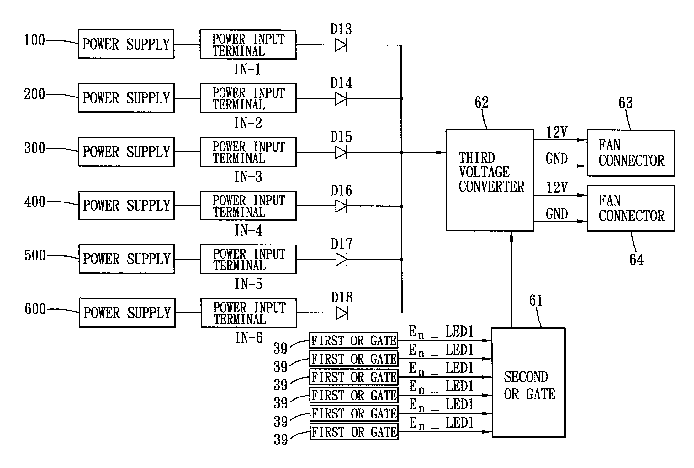
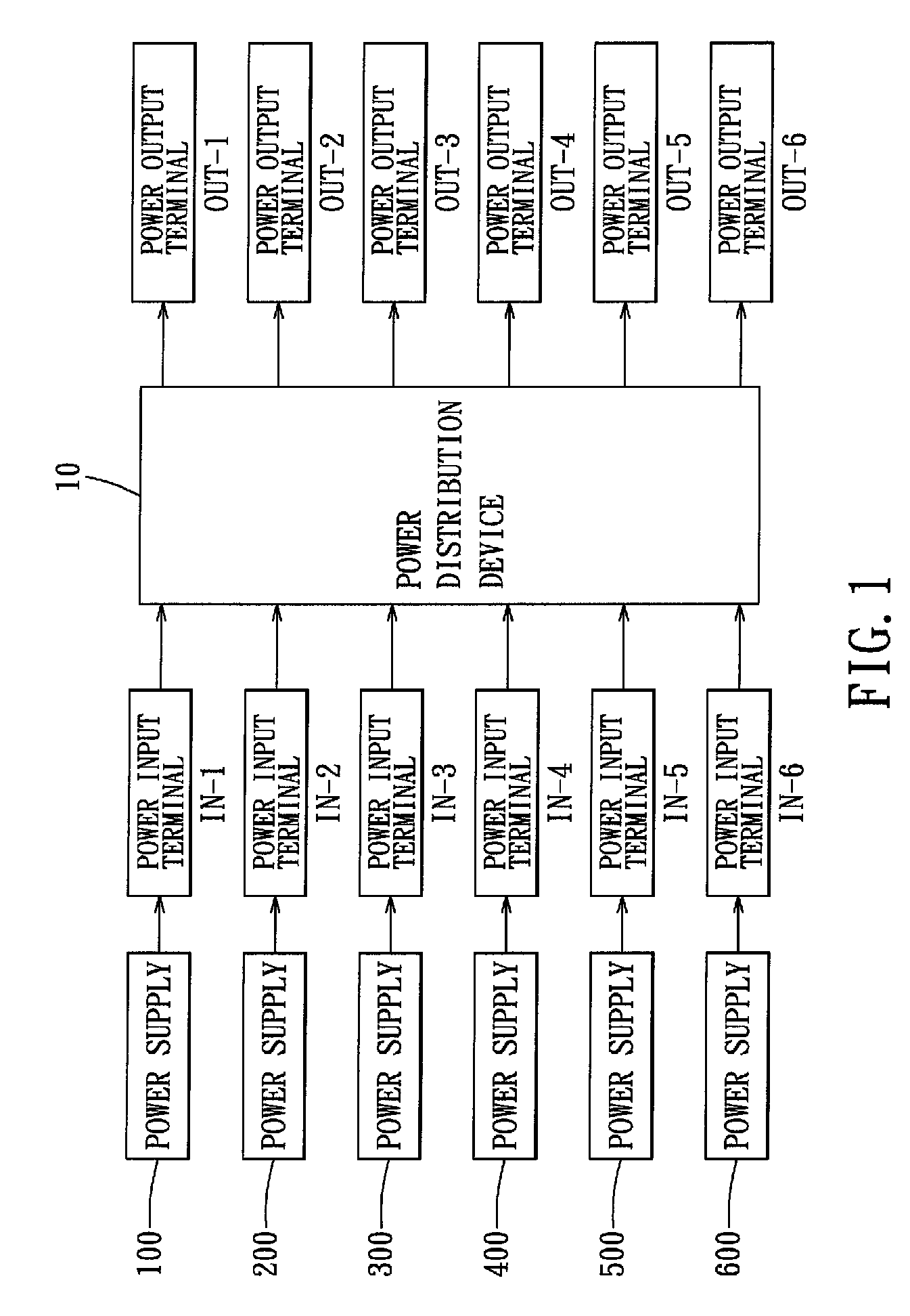
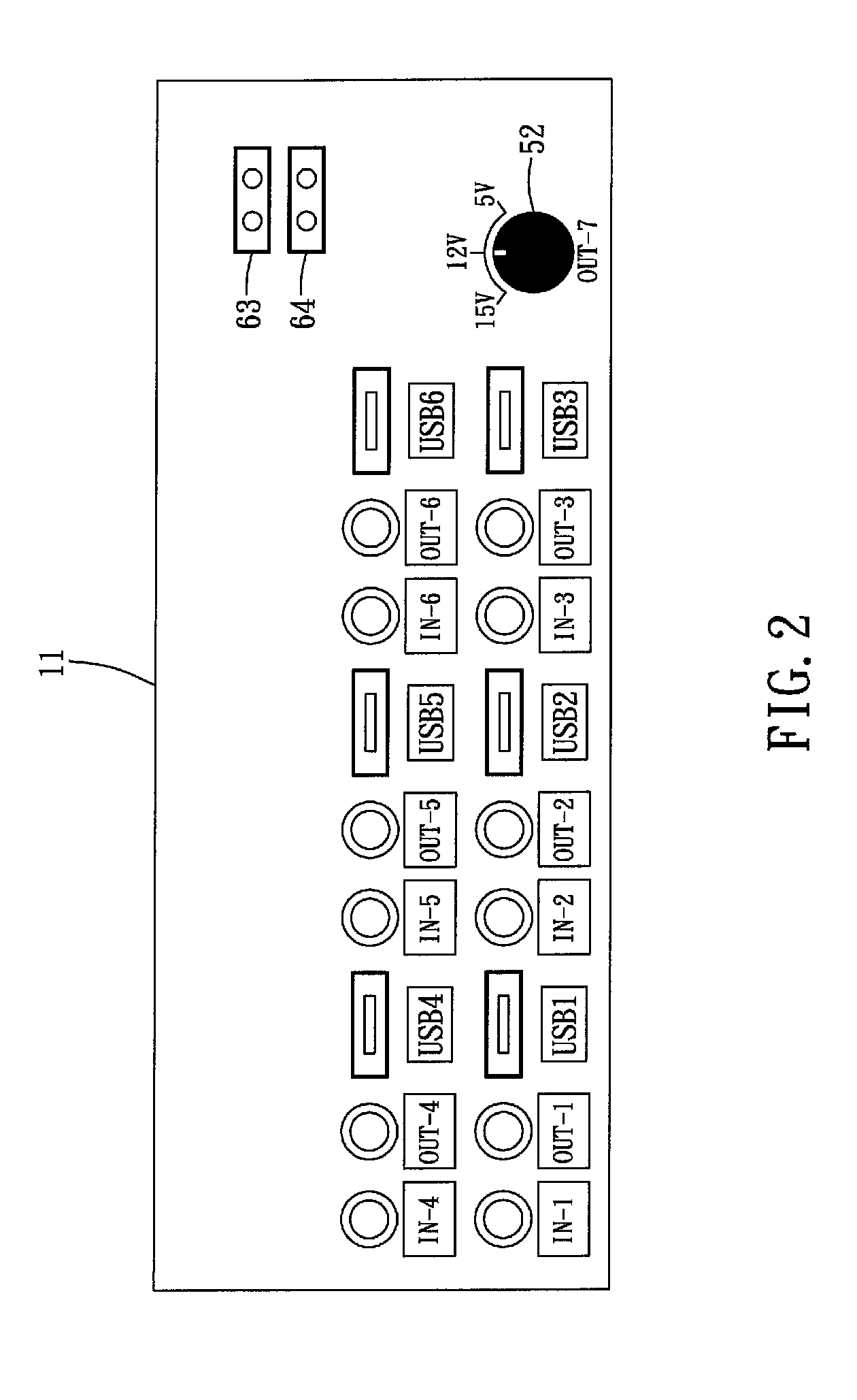
[0033]Referring to FIG. 1 to FIG. 3g, a first embodiment of a power distribution device 10 of the present invention includes a number (N, in which N is a positive integer not less than 2) of power input terminals each to be electrically coupled to a corresponding power supply, and a number (M, in which N is a positive integer not less than 2) of power output terminals each to be electrically coupled to a corresponding electronic device so as to output power thereto. In this embodiment, with reference to a casing back panel 11 of the power distribution device 10 illustrated in FIG. 2, it is given as an example that six (i.e., N=6, and first to sixth) power input terminals IN-1˜IN-6 and six (i.e., M=6) power output terminals OUT-1˜OUT-6 are provided for the powe...


PUM


Abstract

A power distribution device includes a number (N, N≧2) of power input terminals, a number (M, M≧2) of power output terminals, and a number (M) of power distribution circuits, each electrically coupled to a corresponding one of the power output terminals and electrically coupled to a number (P, P≧2) of the power input terminals. Each of the power distribution circuits includes a number (P) of diodes each electrically coupled between a respective one of the power input terminals and the corresponding one of the power output terminals, a switch element connected in parallel to one of the diodes, and a controller controlling the switch element to operate in a conducting state when the controller determines that power received at the power input terminal connected to the switch is normal, and controlling the switch element to operate in a non-conducting state when the power is abnormal.

Description

CROSS-REFERENCE TO RELATED APPLICATION[0001]This application claims priority of Taiwanese Application No. 100102837, filed on Jan. 26, 2011, and the disclosures of which is incorporated herein by reference.BACKGROUND OF THE INVENTION[0002]1. Field of the Invention[0003]The present invention relates to a power management device, more particularly to a power distribution device.[0004]2. Description of the Related Art[0005]Owing to progress of technology, desktop personal computers (PCs) have been developed so as to conform to a trend of miniaturization. Mobile chipsets have been adopted to manufacture a power-saving miniaturized personal computer, such as an All-In-One (AIO) personal computer and a mini personal computer available on the market. Since the miniaturized PC adopts the power-saving mobile chipsets, a power adapter used by notebook computers may replace an ATX power supply originally used by personal computers for supplying power. Therefore, there are manufacturers gatheri...

Claims


Application Information

Patent Timeline
Patent Type & Authority Patents(United States)
IPC IPC(8): H02J1/10H02J3/38H02J7/34G06F1/30H02J3/00G06F1/00
CPCG06F1/30H02J3/00G06F1/00Y10T307/305
Inventor CHENG, SHENG-HSIUNGCHANG, TING-YU
Owner AOPEN
Why Eureka
Try Eureka