
Cooking appliance of the grill or barbecue type

a grill or barbecue technology, applied in the field of grill or barbecue grills, can solve the problems of limited efficiency of this type of appliance, high carcinogenicity of toxic smoke containing compounds, and inability to meet the needs of use, and achieve the effects of convenient use, convenient use, and simple design

Active Publication Date: 2016-01-19
AGAPEA SOLUTIONS
View PDF7 Cites 1 Cited by
  • Summary
  • Abstract
  • Description
  • Claims
  • Application Information

AI Technical Summary

Benefits of technology

This patent describes a new barbecue cooking appliance that can be used to cook healthy food without producing harmful smoke. The appliance is simple, compact, easy to clean, and safe to use. It uses infrared radiation to cook the food efficiently and has a design to prevent accidental contact between the food and the appliance.

Problems solved by technology

With this type of configuration in which the cooking surface is above the heating surface, at least some of the cooking juices and fats running from the foodstuffs while they cook inevitably fall onto the heat source located below, and are immediately carbonized, generating toxic smoke containing compounds recognized as being highly carcinogenic.
These compounds may in particular prove especially dangerous when using this type of cooking appliance in a closed environment, such as an apartment.
Furthermore, the cooking appliance described in publication U.S. Pat. No. 3,389,651 may prove dangerous and in particular start a fire due to the type of fuel used or cause burns since no heat protection is planned for the user.
In addition, the efficiency of this type of appliance is limited due to the fact that the foodstuffs are cooked by radiation through perforated sheets, and not directly.
Nevertheless, while it reduces the quantity of toxic smoke caused by carbonization of the fats, this solution is not always entirely satisfactory.
Indeed, it has been observed that the fats running from the foodstuffs placed in the upper part of the cooking surface drip along the foodstuffs placed at lower levels, sometimes causing them to catch fire.
In addition, although to a lesser extent, the fats always splash onto the heating surface, producing smells and other unpleasant fumes.
Consequently therefore, this type of cooking appliance is not suitable for healthy cooking in an indoor environment.
Once again, the problem of toxic smoke is not fully resolved, since the fats always splash onto the electrical element where they are carbonized, emitting smoke and unpleasant smells.
Although it limits the emission of toxic and unpleasant smoke, this type of barbecue nevertheless exhibits several drawbacks such as pollution of the foodstuffs by the combustion products, i.e. the embers and the ashes.
Indeed, it does not remove the risks of burns for the user or the risks of fire due to the use of embers, which also limits its implementation to an outdoor environment and prevents any use in apartment.
In addition, it is very bulky which means that a large storage area is required and it is difficult to transport.
Furthermore, like the devices mentioned above, the traditional cooking appliances of grill or barbecue type are not satisfactory as regards the heat sources commonly implemented.
Wood, in fact, not only has a certain degree of inertia but may also be dangerous.
In addition, numerous traditional cooking appliances of grill or barbecue type operate in an “all or nothing” mode and allow no adjustment of the cooking temperature.
Consequently, the foodstuffs must be monitored constantly during cooking then moved away from the heating surface as soon as the desired degree of cooking has been obtained, offering little flexibility and little possibility of keeping the foodstuffs hot after cooking.

Method used


Image

  • Cooking appliance of the grill or barbecue type
  • Cooking appliance of the grill or barbecue type
  • Cooking appliance of the grill or barbecue type

Examples


Embodiment Construction

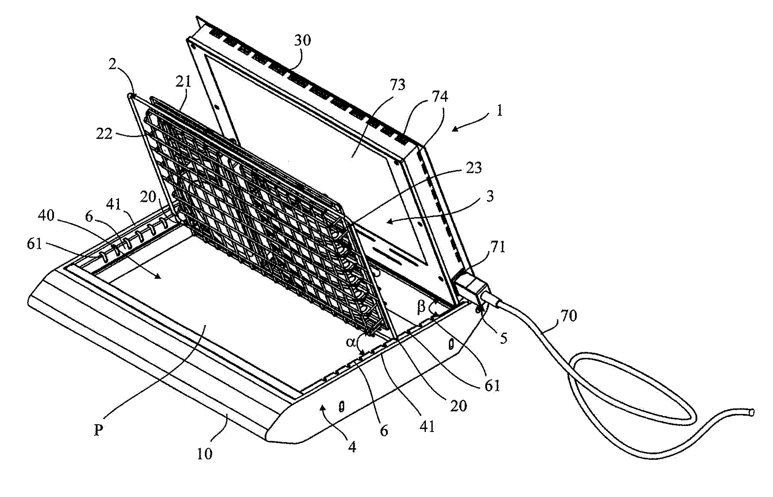
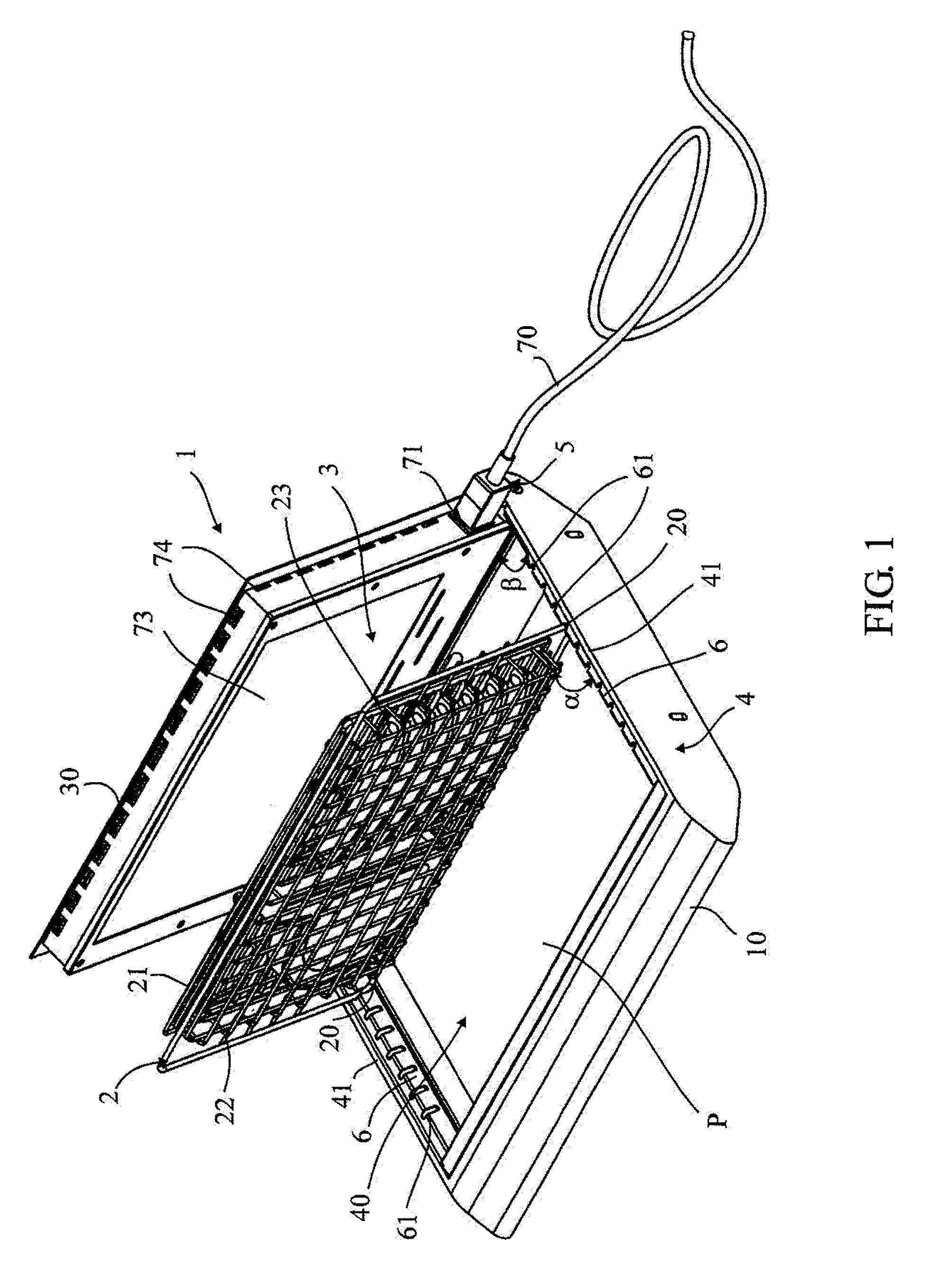
[0037]With reference to the Figures, the invention concerns a cooking appliance 1, 1a used to grill foodstuffs placed on a cooking surface, such as a metal cooking grill 2, using a heating surface 3 arranged opposite said grill 2.

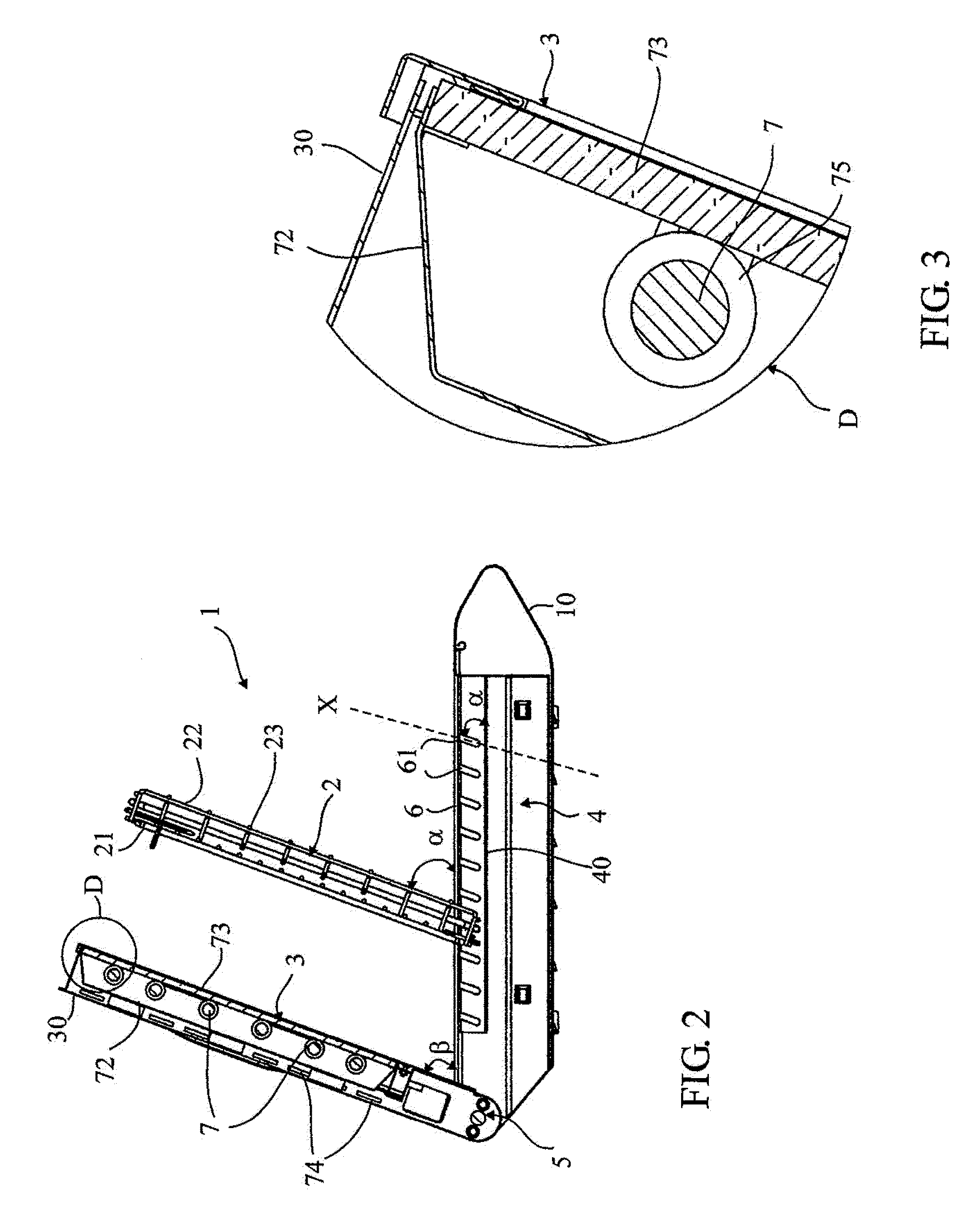
[0038]In the embodiments illustrated on the various figures, the cooking appliance 1, 1a comprises a housing 4 defined by a frame 10, 10a of substantially parallelepipedic shape connected to the heating surface 3 by a hinge 5. The heating surface 3 is connected to a cover 30 and can therefore be displaced between a passive folded position in which the housing 4 is closed (see FIGS. 4, 5 and 7) and an active position in which the housing 4 is open and said heating surface 3 is inclined at an angle β, less than 90°, and for example between 45° and 85°, and for example equal to 70°, to the horizontal plane P formed by the bottom 40 of the housing 4. The hinge 5 is preferably also coupled to means for locking in position, such as for example a ball pusher (not ...


PUM


Abstract

A cooking appliance (1) of the grill or barbecue type, comprises a frame (10) supporting a cooking surface (2) on which foodstuffs to be cooked can be arranged, and a heating surface (3) arranged opposite said cooking surface (2). The frame (10) defines a housing (4) parallel to a horizontal plane (P) and designed to accommodate the cooking surface (2) between a storage position in which it lies on the bottom of the housing (4) and a use position in which it is inclined at an angle α to said horizontal plane (P). The heating surface (3) is connected to the frame (10) by a hinge (5) allowing the displacement of the heating surface (3) between a passive position in which it closes the housing (4) and an active position in which it is inclined at an angle β to the horizontal plane (P), the housing (4) is open and the cooking surface (2) can be deployed and positioned opposite the heating surface (3). The cooking surface (2) is arranged between the horizontal plane (P) and the heating surface (3) so that the substances released by the foodstuffs while they cook do not run onto the heating surface (3).

Description

TECHNICAL FIELD[0001]This invention relates to a cooking appliance of the grill or barbecue type, comprising a frame supporting a cooking surface on which foodstuffs to be cooked can be arranged, and a heating surface arranged opposite said cooking surface, said frame comprising first means designed to allow inclination of said cooking surface with respect to a horizontal plane P at an angle α less than 90°, and second means designed to allow inclination of said heating surface with respect to said horizontal plane P at an angle β less than 90°, said cooking surface being arranged between said horizontal plane P and said heating surface so that the substances released by the foodstuffs while they cook do not run onto said heating surface.BACKGROUND[0002]Numerous cooking appliances of the barbecue or grill type currently exist on the market, intended for the general public or reserved for professional use, the various models differing from each other mainly by the source of heat used...

Claims


Application Information

Patent Timeline
Patent Type & Authority Patents(United States)
IPC IPC(8): A47J27/00A47J37/06A47J37/07H05B6/12A47J37/08
CPCA47J37/07A47J37/0731H05B6/1209
Inventor DI MAURO, DAVIDPARMENTIER, MARC
Owner AGAPEA SOLUTIONS
Learn More