Vane electrostatic precipitator

a precipitator and electrostatic technology, applied in electrostatic separation, solid separation, chemistry apparatus and processes, etc., can solve the problems of poor conductive particulates and difficult collection of high conductive precipitators of the past, and achieve efficient particle collection, low re-entrainment, and high operating air velocity

Inactive Publication Date: 2016-01-19
DUNN JOHN P
View PDF58 Cites 8 Cited by
  • Summary
  • Abstract
  • Description
  • Claims
  • Application Information

AI Technical Summary

Benefits of technology

[0009]The embodiments described herein improve on the present electrostatic precipitator method of using parallel plates to collect particulates by using multiple parallel vanes set at the operating parameters described below. By using vanes, the main entrained air is subdivided and directed to flow between vanes that induce resistance to flow, allowing charged particles to collect on the vanes. The vane is designed to be wide enough so the air flow rate at the ends of the vanes is less than one foot per second (<1 ft / s), allowing particles discharged from the plates to fall by gravity and in the direction of very low air flow, resulting in extremely low re-entrainment and efficient particle collection. Using vanes also allows for higher operating air velocities resulting in a smaller equipment foot print.
[0010]In one embodiment, a method for removing particles from at least one main narrow air stream uses a vane electrostatic precipitator including opposing vane type collecting electrodes. A leading edge of each vane type collecting electrode is offset from an adjacent leading edge such that each vane type collecting electrode is either longer or shorter than a preceding vane type collecting electrode to improve control and efficiency of collection of the particles. The method includes dividing the main narrow air stream into at least two smaller individual air streams in the vane electrostatic precipitator. The smaller individual air streams refer to the air that flows between the vanes. The method also preferably includes a step of dimensioning an input orifice and / or an output orifice and the vane type collecting electrodes to match operational requirements of the main narrow air stream.
[0015]In another embodiment, the main air stream is divided into a number of smaller individual streams in a vane electrostatic precipitator. The vane electrostatic precipitator includes opposing vane type collecting electrodes that are tapered as an assembly from front to back and towards the center of the main air flow of the collection chamber to improve control and efficiency of collection of the particles.

Problems solved by technology

Prior art precipitators have difficulty collecting highly conductive and very poorly conductive particulates.

Method used


Image

  • Vane electrostatic precipitator
  • Vane electrostatic precipitator
  • Vane electrostatic precipitator

Examples


Embodiment Construction

[0023]The terms “vane”, “vane electrode”, and “vane type collecting electrode” are used interchangeably herein.

[0024]Several new factors have been identified as having a major bearing on the collection efficiency of a vane electrostatic precipitator. These include the vane offset, the width of the orifices (with wider orifices, the air flow capacity increases and, in some applications, the length of the field is reduced), the vane assembly angle and the position of discharge electrodes in relation to the leading edges of the vane electrodes.

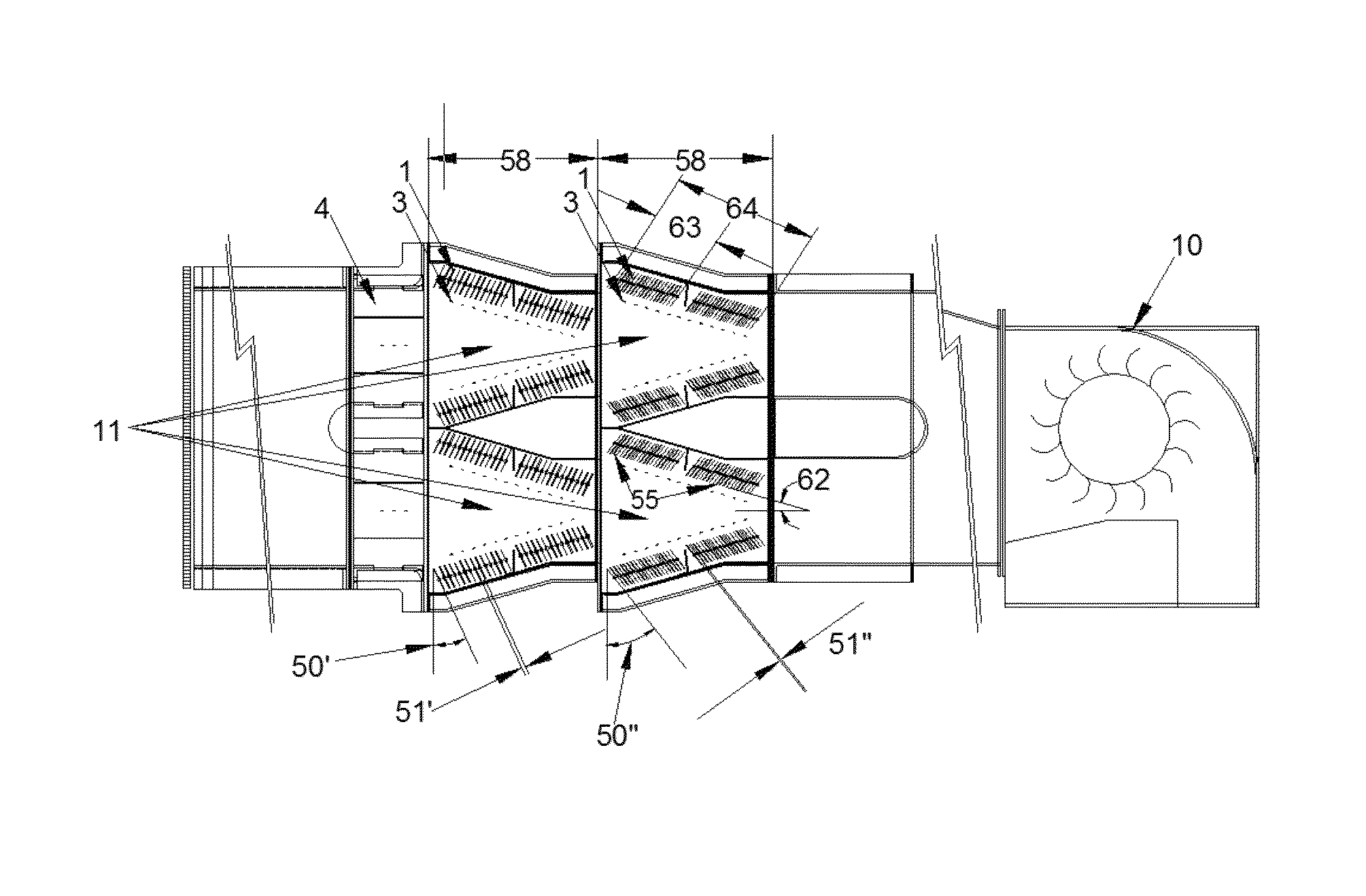
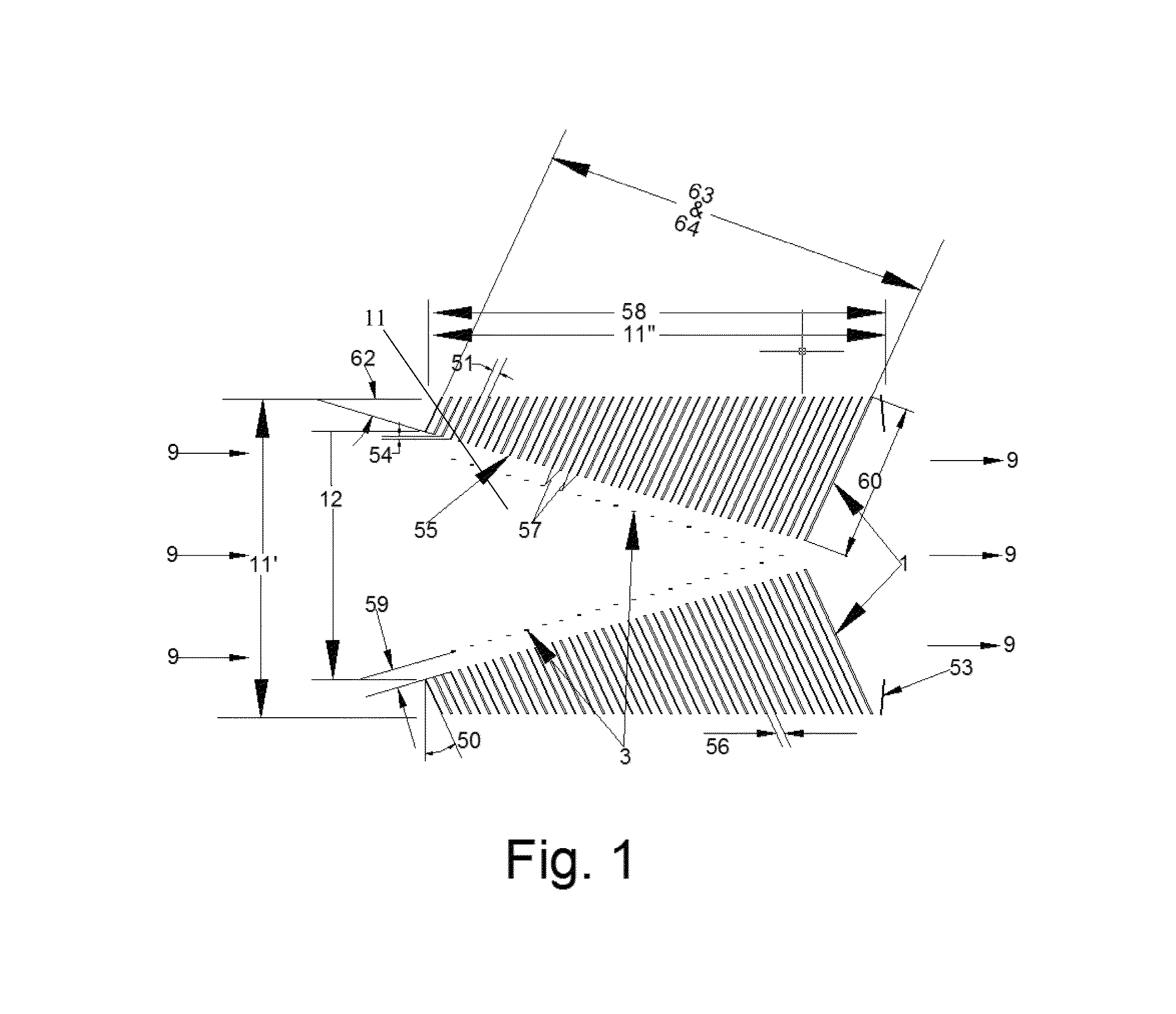
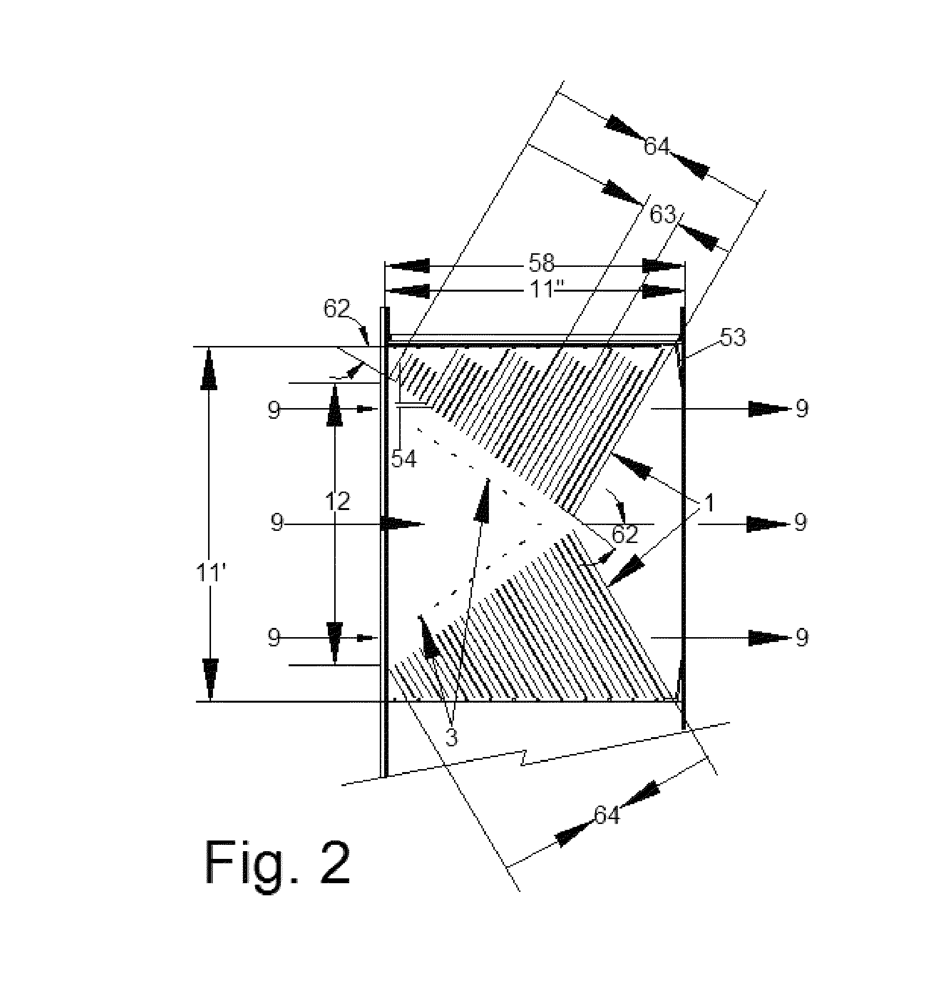
[0025]FIG. 1 shows a vane electrostatic precipitator in an embodiment of the present invention. Air flow (9) enters through an input orifice (12). FIG. 1 shows some of the main factors that affect how the vane electrostatic precipitator functions. These include the vane operating angle (50), the distance (51) between vanes (1), the total vane surface area (53) (which includes the surface area on both sides of each vane) per collection chamber (11...


PUM


Abstract

The embodiments described herein improve on the present electrostatic precipitator method of using parallel plates to collect particulates by using multiple parallel vanes set at operating parameters described below. By using vanes, the main entrained air is subdivided and directed to flow between vanes that induce resistance to flow allowing charged particles to collect on the vanes. The width of the vane is designed to be wide enough so the air flow rate at the ends of the vanes is less than 1 ft / s, allowing particles discharged from the plates to fall by gravity and in the direction of very low air flow, resulting in extremely low re-entrainment and efficient particle collection. Using vanes also allows for higher operating air velocities resulting in a smaller equipment foot print.

Description

REFERENCE TO RELATED APPLICATIONS[0001]This is a continuation-in-part patent application of copending application Ser. No. 13 / 369,823, filed Feb. 9, 2012, entitled “VANE ELECTROSTATIC PRECIPITATOR”, which claims one or more inventions which were disclosed in Provisional Application No. 61 / 521,897, filed Aug. 10, 2011, entitled “VANE ELECTROSTATIC PRECIPITATOR (VEP)”. The benefit under 35 USC §119(e) of the United States provisional application is hereby claimed, and the aforementioned applications are hereby incorporated herein by reference.BACKGROUND OF THE INVENTION[0002]1. Field of the Invention[0003]The invention pertains to the field of electrostatic precipitators. More particularly, the invention pertains to vane electrostatic precipitators.[0004]2. Description of Related Art[0005]U.S. Pat. No. 4,172,028 discloses an electrostatic sieve having parallel sieve electrodes that are either vertical or inclined. The particles are normally introduced into the electric sieve under the...

Claims


Application Information

Patent Timeline
Patent Type & Authority Patents(United States)
IPC IPC(8): B03C3/45B03C3/41
CPCB03C3/45B03C3/41B03C2201/10
Inventor DUNN, JOHN, P.
Owner DUNN JOHN P
Why Eureka
Try Eureka