Toner

a technology of toner and nozzle, applied in the field of toner, can solve the problems of affecting the performance of toner, affecting the development process, and deteriorating toner, and achieve the effects of reducing the occurrence of waste toner spillage, and reducing the amount of toner accumulated

Active Publication Date: 2016-01-19
CANON KK
View PDF13 Cites 44 Cited by
  • Summary
  • Abstract
  • Description
  • Claims
  • Application Information

AI Technical Summary

Benefits of technology

[0019]Such related art has indeed provided a certain degree of advantageous effects in terms of stability when used in durability tests and in terms of the cleaning performance. Yet, in cases where, as described above, the diameter of the developing sleeve has been made smaller, and also in low-temperature environments, satisfactory solutions have not been developed, leaving room for further improvement.
[0020]It is therefore an object of this invention to provide a toner which is able to resolve problems such as those described above.
[0021]More specifically, the object of this invention is to provide a toner which enables good images that have a stable image density and are free of fogging to be obtained regardless of the service environment, and which can suppress faulty cleaning and the occurrence of waste toner spillage even with downsizing of the image-forming apparatus and even under the conditions of use in a long-term durability test.
[0022]The inventors have discovered that the above challenges can be overcome by specifying the external addition state to toner for fine particles of a group 2 element titanate, such as strontium titanate fine particles, and silica fine particles.
[0023]Accordingly, the present invention provides a toner comprising toner particles comprising a binder resin and a colorant, and as external additives, inorganic fine particles A and inorganic fine particles B, wherein
[0024]the inorganic fine particles A are group 2 element titanate fine particles which have a number-average particle diameter (D1) of primary particles thereof, which is not less than 60 nm and not more than 200 nm,

Problems solved by technology

However, the burden on the toner increases at higher speeds, and problems relating to development performance, such as a decline in the image density caused by toner deterioration, have a tendency to arise.
Moreover, in the cleaning step, increasing the process speed of the apparatus makes it difficult for the cleaning blade to properly scrape away the toner, and allows toner to pass by the cleaning blade.
As a result, what is referred to as “faulty cleaning” tends to arise.
In the case of a smaller developing sleeve in particular, the developing zone of the development nip becomes smaller, making it more difficult for toner to jump from the developing sleeve.
As a result, the phenomenon known as “charge-up” occurs in which only a portion of the toner becomes excessively charged, sometimes causing various image defects.
For example, the charged up toner remains on the developing sleeve, leading to a decrease in image density and making charging of the toner non-uniform, as a result of which image defects such as fogging in non-image regions sometimes arises.
In addition, the charged up toner tends to adhere strongly to the photosensitive member, making it difficult to remove in the cleaning step, which readily leads to faulty cleaning.
Also, such toner has a tendency to pack tightly at the back of the cleaning blade, as a result of which the untransferred toner is not completely recovered, readily giving rise to the problem of waste toner spillage.
Such problems can become quite serious, particularly in low-temperature, low-humidity environments where which toner charge-up readily occurs.
However, simply increasing the blade pressure tends instead to give rise to such problems as vibration and curling of the cleaning blade.
Also, from a downsizing standpoint, because making the photosensitive member smaller increases the curvature at the surface of the photosensitive member, stable scraping with the cleaning blade becomes more difficult to achieve.
However, with increasingly fine toner particles targeted at higher image quality, it becomes more difficult to obtain a stable image density.
Moreover, because the state of attachment by silica and other inorganic fine particles is not controlled, this approach has not led to an improvement in cleaning performance within low-temperature, low-humidity environments.
When the diameter of a developing sleeve is made smaller, as mentioned above, charged up toner readily forms and toner charging tends to become uneven.
However, deteriorated toner has a poor ability to circulate, and so proper triboelectric charging of the overall toner tends to be difficult.
Yet, in cases where, as described above, the diameter of the developing sleeve has been made smaller, and also in low-temperature environments, satisfactory solutions have not been developed, leaving room for further improvement.

Method used


Image

  • Toner
  • Toner
  • Toner

Examples


example 1

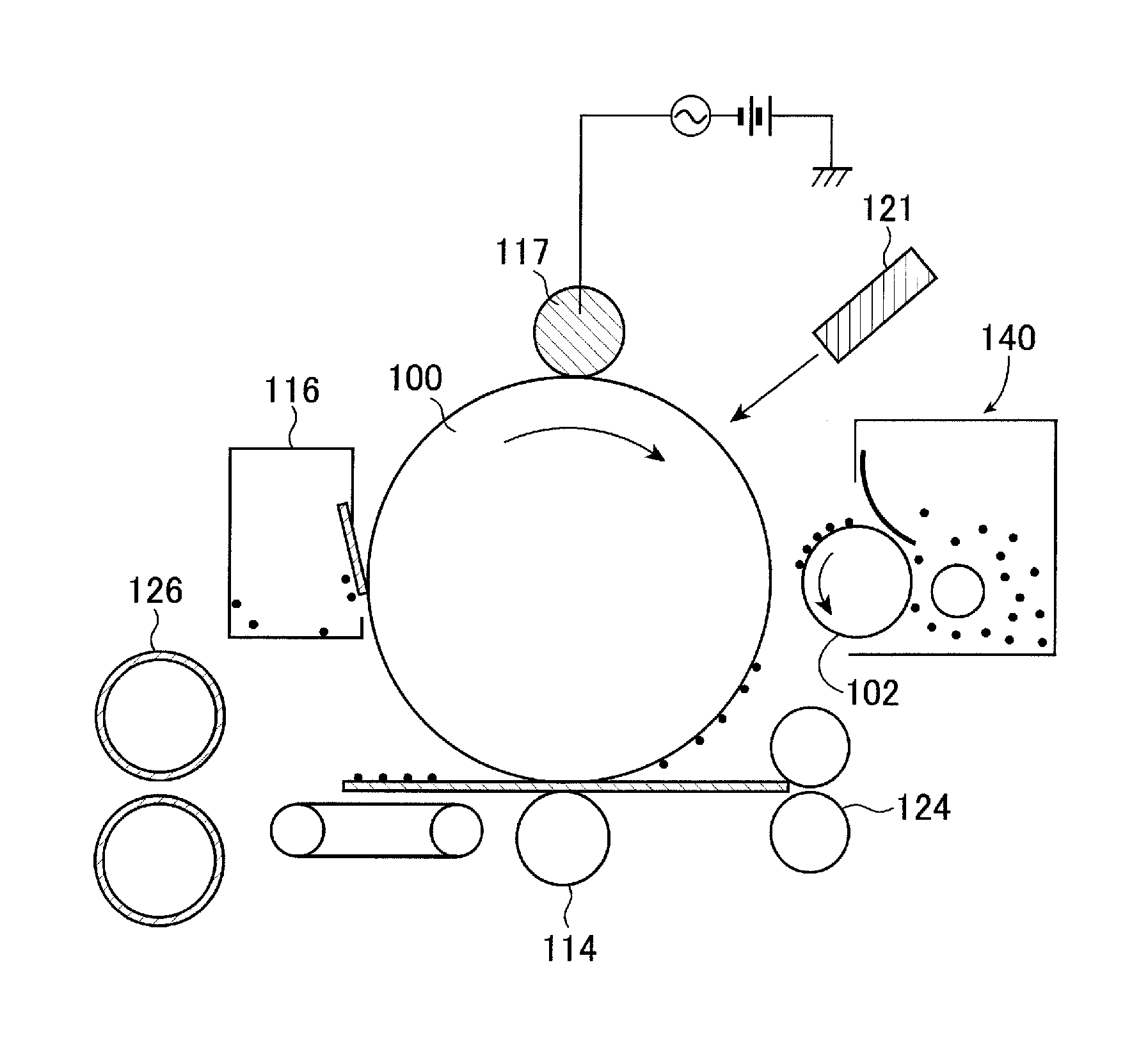
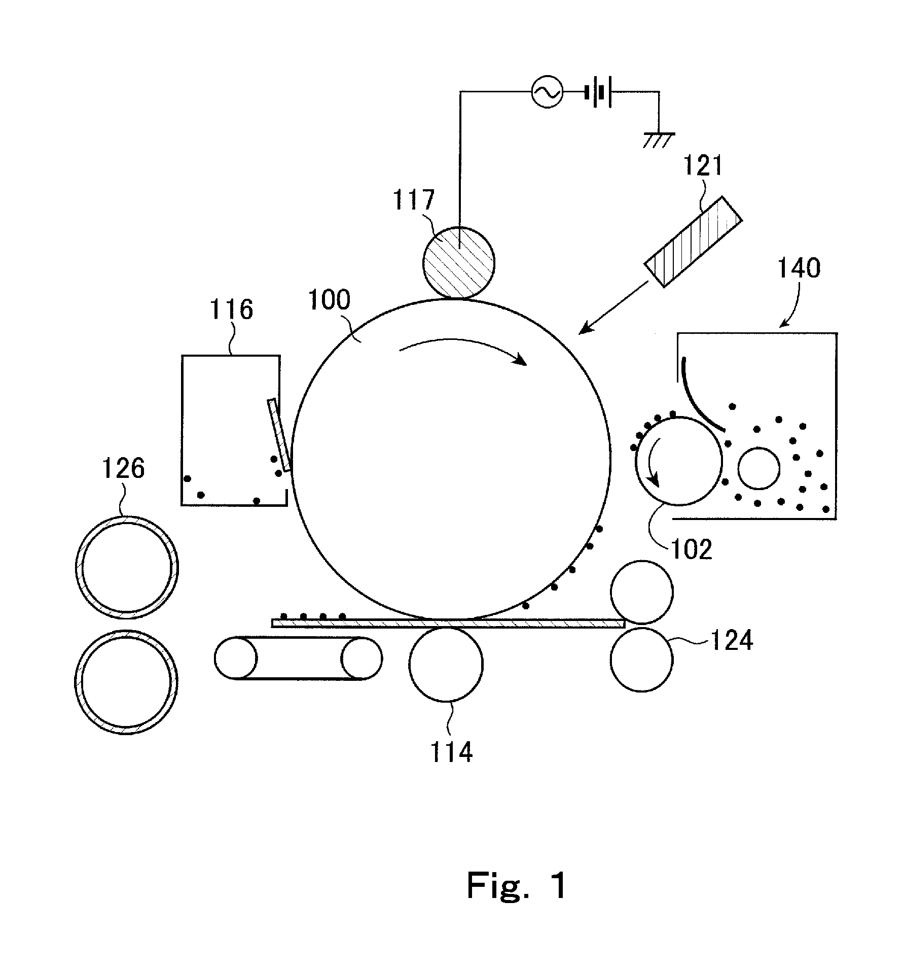
[0374]An LBP-6300 (Canon Inc.) was used as the image-forming apparatus, and the process speed was increased about 1.5 times to 300 mm / sec.

[0375]The 14 mm diameter developing sleeve in the above apparatus was replaced with a developing sleeve having a diameter of 10 mm, the 24 mm diameter photosensitive member was replaced with a photosensitive member having a diameter of 18 mm, and the new developing sleeve and photosensitive member were each loaded into a toner cartridge. In addition, a modified cartridge was used in which the toner filling capacity was increased 1.2-fold and the cleaning blade contact pressure was lowered to about one-half the value at 3 kgf / m.

[0376]In the image-forming apparatus in which the small-diameter developing sleeve has been installed, the image density and fogging that result from toner deterioration can be rigorously evaluated by increasing the process speed. In addition, using the small-diameter photosensitive member, faulty cleaning can be rigorously ...

examples 2 to 30

, Comparative Examples 1 to 12

[0394]In Examples 2 to 30, evaluations were carried out in the same way as in Example 1, but using Toners 2 to 30 instead of Toner 1. Likewise, in Comparative Examples 1 to 12, evaluations were carried out using Comparative Toners 1 to 12. As a result, in substantially all the comparative toners, the image density during the last half of use in durability tests worsened to an undesirable level. The evaluation results are shown in Table 7.

[0395]

TABLE 7Image densityImage density(start of(second half ofFaultyWaste tonerdurability test)durability test)FoggingcleaningspillageExample 1Toner 1A (1.48)A (0.06)A (0.3)AAExample 2Toner 2A (1.49)A (0.05)A (0.4)AAExample 3Toner 3A (1.49)A (0.05)A (0.3)AAExample 4Toner 4A (1.49)A (0.05)A (0.3)AAExample 5Toner 5A (1.48)A (0.06)A (0.7)AAExample 6Toner 6A (1.48)A (0.06)A (0.5)AAExample 7Toner 7A (1.46)A (0.08)A (0.8)AAExample 8Toner 8A (1.45)A (0.09)A (0.7)BAExample 9Toner 9A (1.47)A (0.09)A (0.8)AAExample 10Toner 10A (...


PUM

PropertyMeasurementUnit
number-average particle diameteraaaaaaaaaa

Abstract

A toner comprising toner particles which comprise a binder resin and a colorant, and also inorganic fine particles as external additives, wherein the inorganic fine particles are silica fine particles and a group 2 element titanate fine particles, the inorganic fine particles have specific particle diameters, the silica fine particles have a coverage ratio X1 on the surfaces of the toner particles, which is not less than 40.0 surface area % and not more than 75.0 surface area %, when the theoretical coverage ratio by the silica fine particles is X2, the diffusion index defined as “diffusion index=X1 / X2” satisfies the condition: diffusion index≧−0.0042×X1+0.62, and the external additives have an embedding ratio on the toner particles, which satisfies a specific range.

Description

BACKGROUND OF THE INVENTION[0001]1. Field of the Invention[0002]The present invention relates to a toner for use in, for example, electrophotographic, electrostatic recording and magnetic recording technologies.[0003]2. Description of the Related Art[0004]Conventionally, in electrophotographic systems, an electrostatic latent image bearing member (referred to below as a “photosensitive member”) which is generally composed of a photoconductive material is charged by various means then exposed to light, thereby forming an electrostatic latent image on the surface of the photosensitive member. Next, the electrostatic latent image is developed with toner on a toner bearing member (referred to below as a “developing sleeve”) to form a toner image, and the toner image is transferred to a transfer material such as paper, following which the toner image is fixed on the transfer material by heat, pressure or the application of both heat and pressure, yielding a copied article or a print. At ...

Claims


Application Information

Patent Timeline
Patent Type & Authority Patents(United States)
IPC IPC(8): G03G9/08G03G9/087G03G9/097
CPCG03G9/0821G03G9/08G03G9/0804G03G9/087G03G9/0827G03G9/09708G03G9/09725
Inventor HASEGAWA, YUSUKEMATSUI, TAKASHIHIROKO, SHUICHISUZUMURA, YOSHITAKAOHMORI, ATSUHIKOTANAKA, KEISUKE
Owner CANON KK
Why Eureka
Try Eureka