Distortion reduced signal detection

a technology of distortion reduction and signal detection, applied in the field of characteristic signal extraction, can solve the problems of reducing the processing accuracy of desired signals, affecting the accuracy of data extraction, etc., and achieve the effect of improving accuracy

Active Publication Date: 2016-01-26
KONINKLJIJKE PHILIPS NV
View PDF7 Cites 1 Cited by
  • Summary
  • Abstract
  • Description
  • Claims
  • Application Information

AI Technical Summary

Benefits of technology

[0013]It is therefore an object of the present invention to provide a system and a method for extracting information from detected characteristic signals providing further refinements facilitating obtaining the desired signals with higher accuracy.
[0014]Furthermore, it would be advantageous to provide a device and method even adapted for enabling an extraction of the desired signals under considerably poor ambient conditions, e.g. small signal-to-noise ratio, varying luminance conditions and / or steady or even unsteady movements of the object to be observed. It would be further advantageous to provide a device adapted for being less susceptible to disturbances influencing the captured signals to be processed and analyzed.

Problems solved by technology

Hence, a detailed precise extraction of the desired signals still poses major challenges for the processing of such data.
Although considerable progress in the field of computing performance has been made, it is still a challenge to provide for instant image recognition and image processing enabling immediate, so to say, on-line detection of desired vital signals.
This applies in particular to mobile device applications commonly lacking of sufficient computing power.
Furthermore, data transmission capacity can be restricted in several applications.
However, such laboratory conditions cannot be transferred to everyday field applications as high efforts and preparation work would be required therefor.
After all, vital signal detection is made even more difficult when amplitudes and / or nominal values of disturbing signal components are much larger than amplitudes and / or nominal values of desired signal components to be extracted.

Method used


Image

  • Distortion reduced signal detection
  • Distortion reduced signal detection
  • Distortion reduced signal detection

Examples


Embodiment Construction

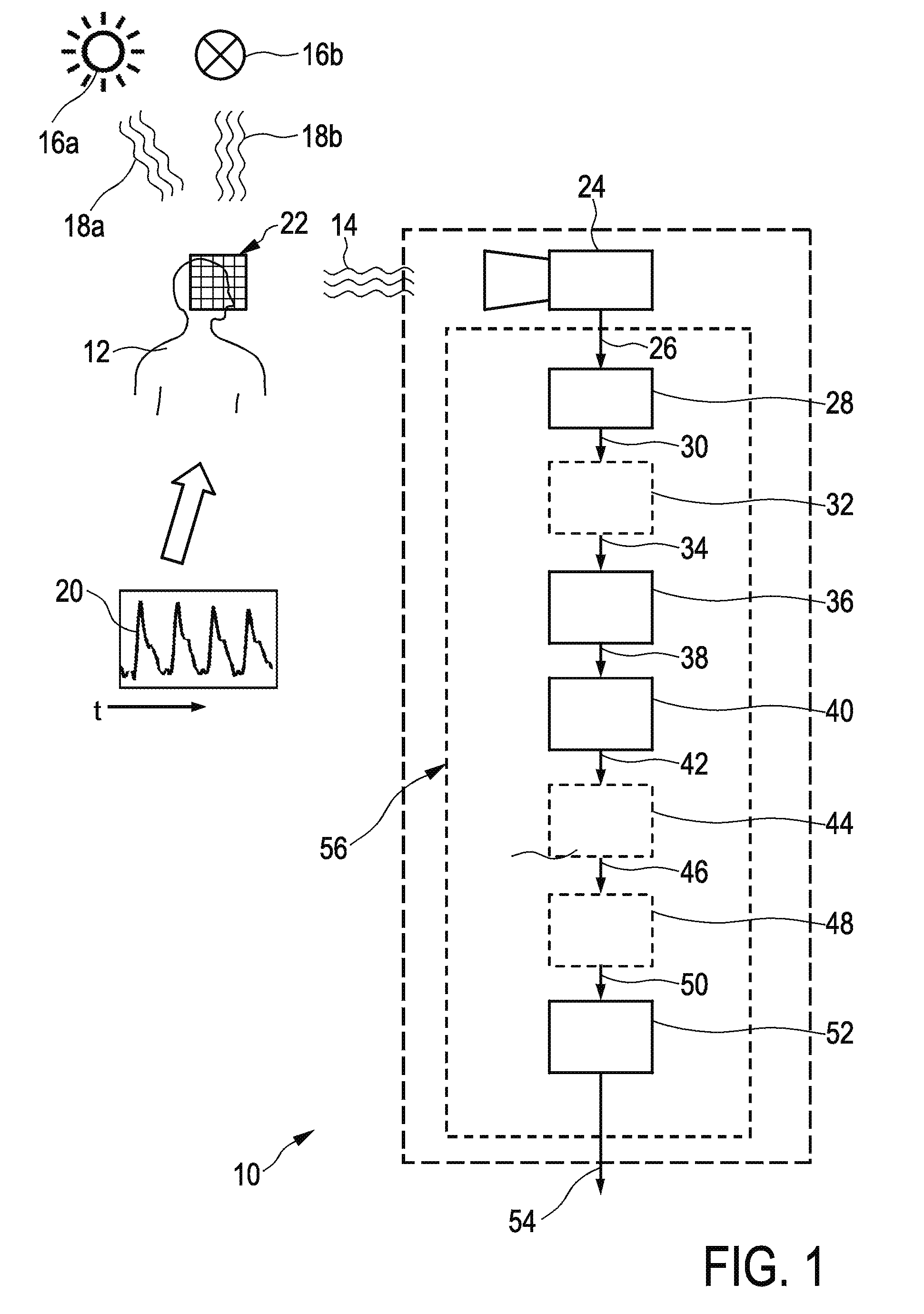
[0075]FIG. 1 shows a schematic illustration of device for extracting information which is denoted by a reference numeral 10. For instance, the device 10 can be utilized for recording or processing image frames representing a remote object 12 for remote PPG monitoring. The image frames can be derived from electromagnetic radiation 14 reflected by the object 12. The object 12 can be a human being or animal, or, in general, a living being. Furthermore, the object 12 can be part of a human being highly indicative of a desired signal, e.g., a face portion, or, in general, a skin portion.

[0076]A source of radiation, such as sunlight 16a or an artificial radiation source 16b, also a combination of several radiation sources can affect the object 12. The radiation source 16a, 16b basically emits incident radiation 18a, 18b striking the object 12. For extracting information from the recorded data, e.g. a sequence of image frames, a defined part or portion of the object 12 can be detected by a...


PUM


Abstract

The present invention relates to a device and a method for extracting information from detected characteristic signals. A data stream (26) derivable from electromagnetic radiation (14) emitted or reflected by an object (12) is received. The data stream (26) comprises a continuous or discrete time-based characteristic signal ( ; 98) comprising at least two main components (92a, 92b, 92c) related to respective complementary channels (90a, 90b, 90c) of a signal space (88). The characteristic signal ( ; 98) is mapped to a defined component representation ( , , , ; , ) under consideration of a substantially linear algebraic signal composition model so as to specify a linear algebraic equation. The linear algebraic equation is at least partially solved under consideration of an at least approximate estimation of specified signal portions ( , , ). Consequently, an expression highly indicative of the at least one at least partially periodic vital signal (20) can be derived from the linear algebraic equation.

Description

FIELD OF THE INVENTION[0001]The present invention relates to a device and method for extracting information from characteristic signals, wherein the characteristic signals are embedded in a data stream derivable from electromagnetic radiation, in particular wherein the data stream comprises a continuous or discrete time-based characteristic signal, wherein the characteristic signal comprises at least two main components associated with a signal space, the signal space comprising complementary channels for representing the characteristic signal, the main components of the characteristic signal being related to respective complementary channels of the signal space. The invention further addresses distortion reduced signal detection.BACKGROUND OF THE INVENTION[0002]WO 2011 / 021128 A2 discloses a method and a system for image analysis, including:[0003]obtaining a sequence of images;[0004]performing a vision-based analysis on at least one of the sequence of images to obtain data for class...

Claims


Application Information

Patent Timeline
Patent Type & Authority Patents(United States)
IPC IPC(8): G06K9/00G06K9/62G06K9/20A61B5/1455A61B5/00A61B5/024G06V10/143
CPCA61B5/7235A61B5/0075A61B5/02416A61B5/14551G06K9/2018G06K9/624G06T7/0016G06T2207/30076G06V10/143G06V10/7715G06F18/2134
Inventor VAN, LEEST, ADRIAAN, JOHAN
Owner KONINKLJIJKE PHILIPS NV
Why Eureka
Try Eureka