
Method and device for purifying fluid media by removal of contaminating multicomponent ingredients

a technology of multi-component ingredients and purification method, which is applied in the direction of vortex flow apparatus, flat flow vortex, separation process, etc., can solve the problems of narrow range of contaminants removed from gaseous flow, high gas purification degree, and increasing environmental pollution proportionally to the rise of production

Inactive Publication Date: 2016-01-26
ABAYEV ALEXANDR DZAKHOTOVICH +2
View PDF17 Cites 3 Cited by
  • Summary
  • Abstract
  • Description
  • Claims
  • Application Information

AI Technical Summary

Benefits of technology

[0013]The technical task to be solved by the present invention is to provide the maximum purification degree of fluid media (liquid or gas) to remove contaminating multicomponent ingredients.

Problems solved by technology

In industrial countries, pollution of the environment is growing proportionally to the rise of production.
Nevertheless, the gas purifying means recover only a part of atmosphere contaminating substances contained in the gases removed from technological units with a gas purification system.
However, said trap separator is characterized by a very narrow range of solid fractions that it traps from a gas flow, which highly reduces the gas purification degree.
The main drawback of said spiral separator is the narrow range of contaminants removed from the gaseous flow, in the considered case it is only liquid, said range being limited by the size of the porous material capillaries.

Method used


Image

  • Method and device for purifying fluid media by removal of contaminating multicomponent ingredients
  • Method and device for purifying fluid media by removal of contaminating multicomponent ingredients
  • Method and device for purifying fluid media by removal of contaminating multicomponent ingredients

Examples


Embodiment Construction

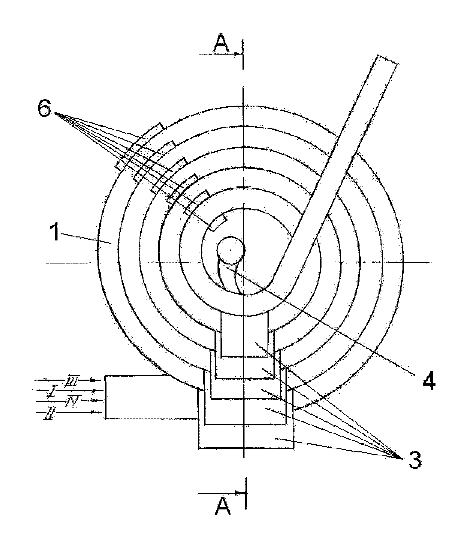
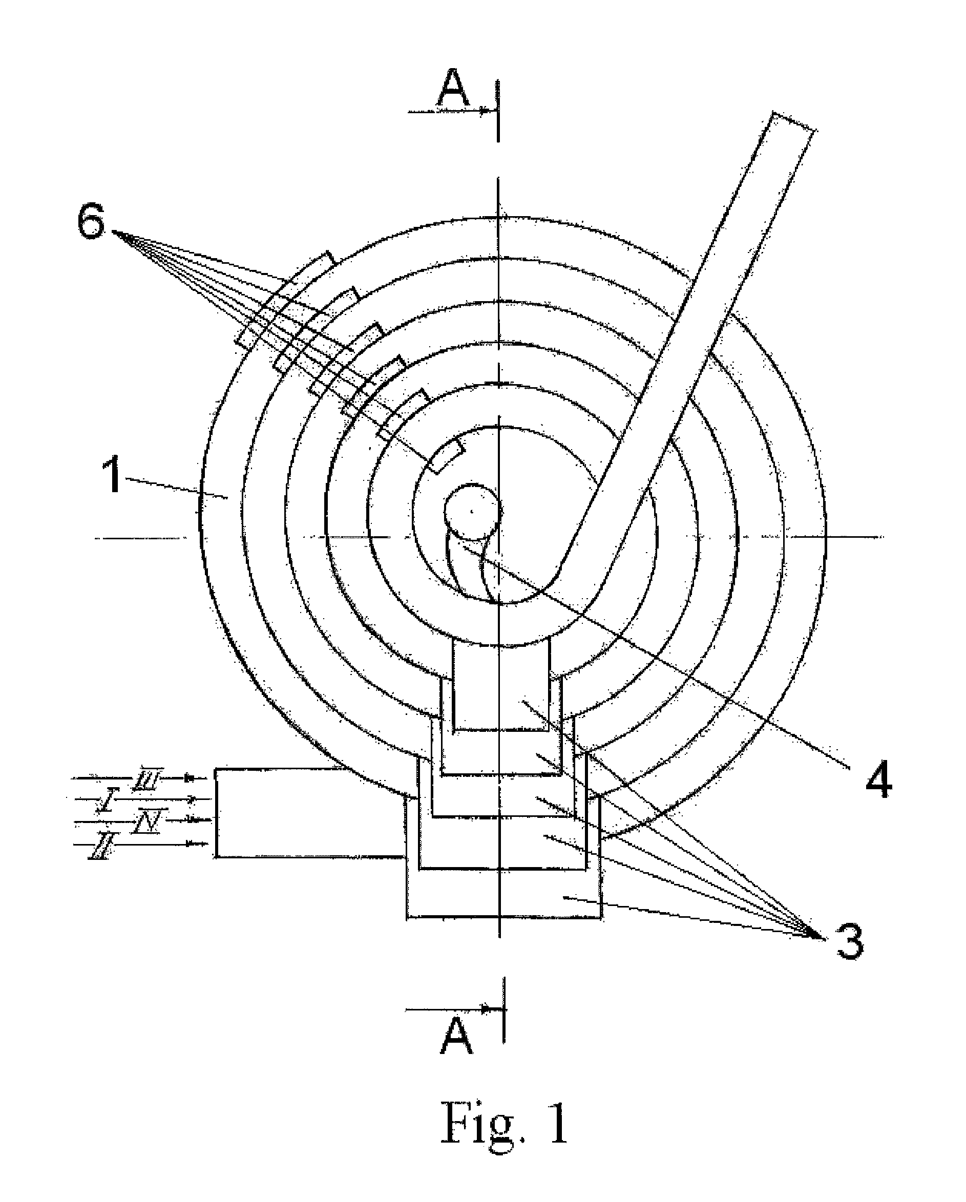
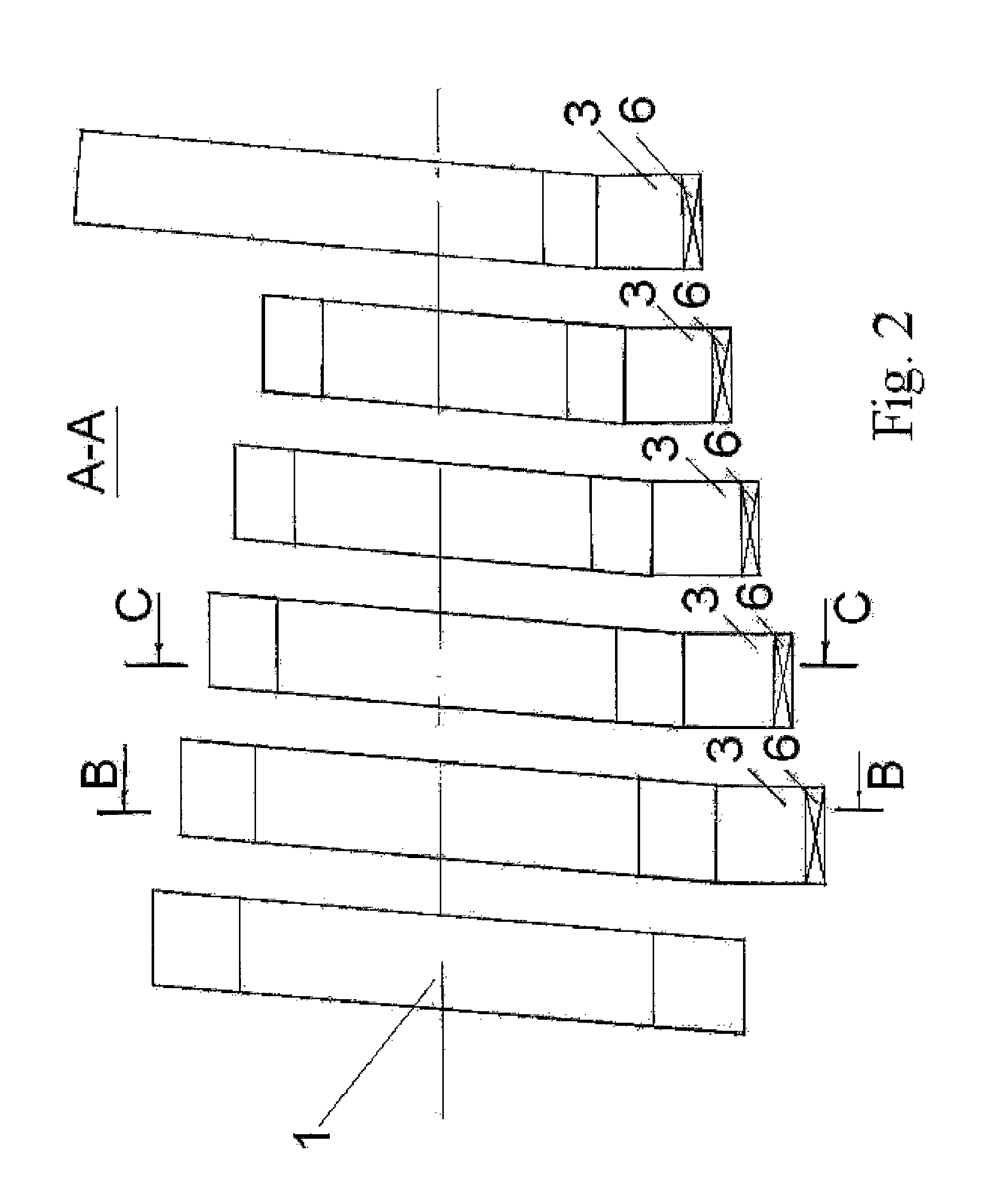
[0036]As shown in FIG. 1, the device for purifying fluid media by removal of contaminating multicomponent ingredients comprises a housing composed of at least one hollow spiral element 1 every turn of which presents, for example, a rectangular section and communicates, via a separation opening 2 provided at the outer surface of the same (FIGS. 3, 4), with a corresponding separation chamber 3. A nozzle 4 designed to compensate the mass and the centrifugal moment of the fluid media is provided from the inner side of each coil of the spiral element opposite the corresponding separation opening 2.

[0037]On the nozzle wall 4 there is mounted, for example, with the help of a hinge, an element 5 guiding the fluid media flow to the separation opening 2 and having a streamlined form, for example such as shown in FIGS. 3 and 4. The size of the element 5, as well as that of the separation opening 2 can be selected according to given parameters of a particular technological purification process,...


PUM

PropertyMeasurementUnit
massaaaaaaaaaa
areaaaaaaaaaaa
chemicalaaaaaaaaaa

Abstract

The group of inventions relates to the technology for purifying liquids and gases by removal of contaminating multicomponent ingredients. The device comprises a housing comprising at least one hollow spiral element with a conical shape, with separation openings being formed in at least some of the turns of the spiral element, each of the openings communicating with a corresponding separation chamber. Arranged opposite the separation opening is a nozzle, which is intended for compensating for the mass and centrifugal moment of the fluid medium. A guide element around which a flow passes is mounted on the wall of the nozzle. The cross-sectional area and the radius of each successive turn is selected from the condition for maintaining an estimated value for the centrifugal moment of the substance to be purified. The method consists in that a flow of medium to be purified is spun by the above-described device. Contaminating components in each turn are positioned by coaxial layers. Layer-by-layer removal of the contaminating components via the separation openings is performed. A reduction in the centrifugal moment of the flow to be purified is compensated for by a clean layer of fluid medium being injected. Technical result: as complete purification of fluid media as possible.

Description

CROSS REFERENCE TO RELATED APPLICATIONS[0001]This application is the National Stage of PCT / RU2012 / 000553 filed on Jul. 9, 2012, which claims priority under 35 U.S.C. §119 of Eurasian Application No. 201200796 filed on Dec. 2, 2011, the disclosure of which is incorporated by reference. The international application under PCT article 21(2) was not published in English.FIELD OF THE INVENTION[0002]The group of inventions relates to the technology of purifying liquids and gases by removal of contaminating multicomponent ingredients and can find application in various branches of industry, in particular such as flour milling or building industries while purifying various wastes.BACKGROUND OF THE INVENTION[0003]In industrial countries, pollution of the environment is growing proportionally to the rise of production.[0004]To recover some contaminating ingredients from liquids and gases (hereinafter fluids), depending on their properties and those of the fluid media to be purified, use is ma...

Claims


Application Information

Patent Timeline
Patent Type & Authority Patents(United States)
IPC IPC(8): B01D45/12B01D45/16B01D50/00B01D45/08B04C5/13B01D53/24
CPCB01D45/16B01D45/08B01D45/12B01D50/002B01D53/24B04C5/13B04C1/00B01D50/20
Inventor ABAYEV, ALEXANDR DZAKHOTOVICHABAYEVA, MARINA ALEXANDROVNAKOKOYTI, TAYMURAZ KHADZHISMELOVICH
Owner ABAYEV ALEXANDR DZAKHOTOVICH
Learn More