Conversion of natural gas

a natural gas and conversion technology, applied in the field of natural gas conversion, can solve the problems of erosive entrained catalyst, catalyst movement, catalyst fine formation associated with reactivity loss, etc., to facilitate simultaneous reaction kinetics and distillation product work up, improve the gtl process, and facilitate the effect of fischer-tropsch reaction

Active Publication Date: 2016-01-26
ASA ENERGY CONVERSIONS
View PDF84 Cites 0 Cited by
  • Summary
  • Abstract
  • Description
  • Claims
  • Application Information

AI Technical Summary

Benefits of technology

[0031]We have found a way to significantly improve the GTL process in comparison with previous processes, including the fourth generation slurry phase processes. The invention uses a catalytic distillation column to facilitate the Fischer-Tropsch reaction. This reaction method may utilise a conventional Fischer-Tropsch catalyst in packed sections within the distillation column to facilitate simultaneous reaction kinetics and distillation product work up. Continuous removal of reaction products, specifically water from the reaction zone by means of distillation separation, forces the reaction in the forward direction with significantly improved kinetics. The fractionation of products within the catalyst zones also simplifies further product work up. The fractionation steps and hydro-treating catalyst (noble metal—i.e. a metal resistant to corrosion and oxidation, such as platinum, gold, palladium, silver, osmium, rhodium, ruthenium and iridium—on alumina substrate) within sections of the packed beds facilitate further product work-up and treatment to specification.

Problems solved by technology

This leads to catalyst movement, abrasion and eventually to catalyst fines formation associated with reactivity loss.
A further drawback is that the entrained catalyst is erosive and thinning of the overheads bend sections compromise plant integrity.
The catalyst is continuously moving in a fluidised state and therefore prone to catalyst fines generation and abrasion.
This leads to lowered catalyst activity in the bed.
Although less of a concern than moving or fluid bed reactors, there is still an activity loss.
In particular, the packing of pelleted catalyst in a structured wire mesh packing material is described, which packing provides for a low separation efficiency.
More particularly, the presence of such “teabag”-type packing of catalyst provides for poor distillation.
Vapour channelling and “hot-spot” control (i.e. localised regions of excessive temperature) is difficult.
As a result, operating parameters are not easily tightly controlled within the distillation versus reactive sections due to poor distillation.
The reaction and distillation takes place in two separate vessels, meaning multistage separation within the catalyst zone is not possible, leading to an overall lower conversion and separation efficiency.

Method used


Image

  • Conversion of natural gas
  • Conversion of natural gas
  • Conversion of natural gas

Examples


Embodiment Construction

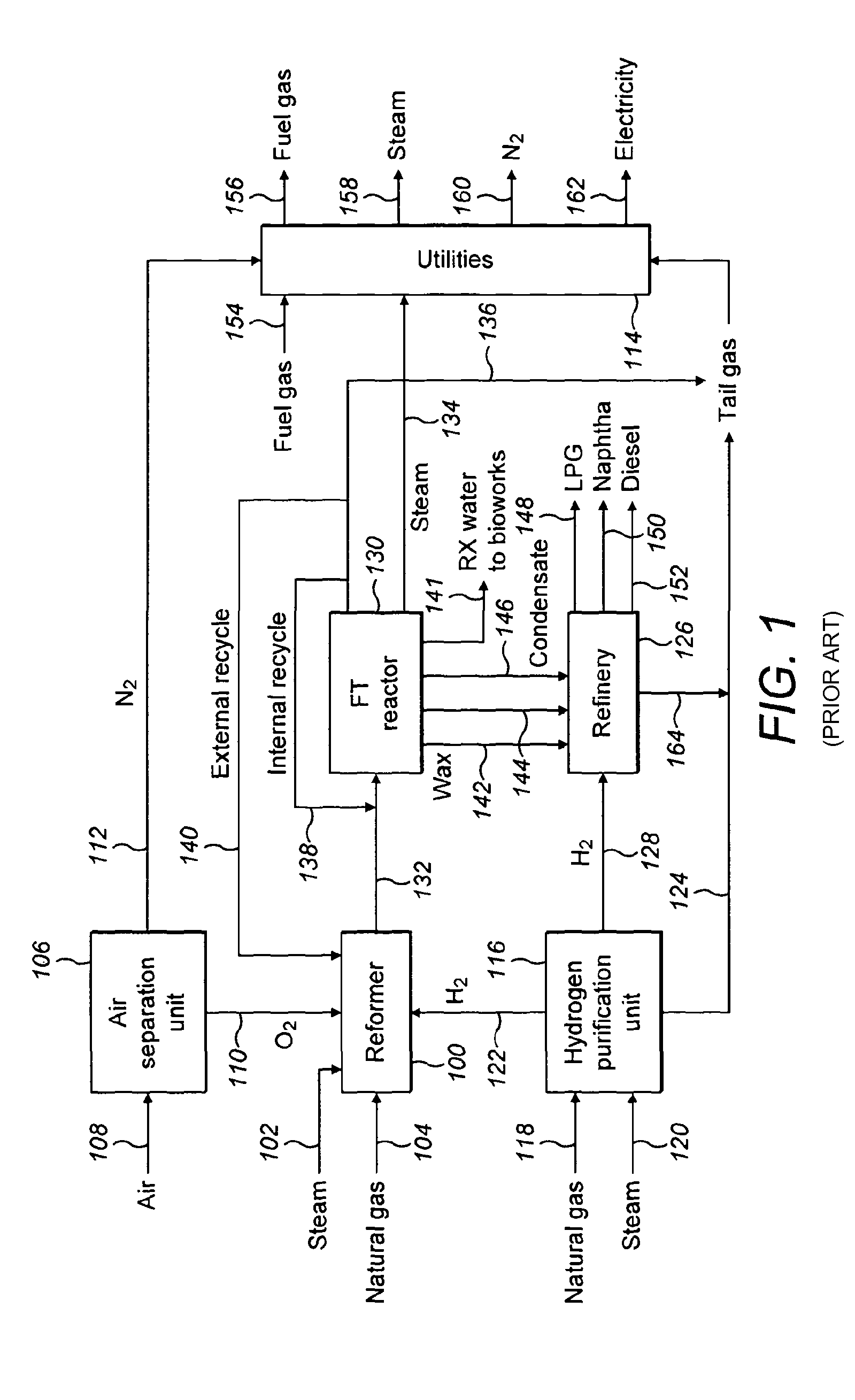
[0041]Referring to FIG. 1 a prior art process and apparatus is shown.

[0042]Natural gas and steam are fed to a reformer 100, via streams 102 and 104 respectively. Air is fed to an air separation unit 106 via stream 108, where it is separated into an oxygen rich stream 110 and a nitrogen rich stream 112. The nitrogen rich stream 112 is fed to the plant utilities, which are generally designated 114.

[0043]Natural gas and steam are also fed to a hydrogen purification unit 116, via streams 118 and 120 respectively. The unit 116 outputs hydrogen via stream 122, which is fed to the reformer 100. The unit 116 also outputs tail gas via stream 124, which is fed to the utilities 114. These streams typically contain a mixture of hydrogen and light hydrocarbons that makes up a low to medium calorific value fuel gas that can be used to as utility gas around the complex.

[0044]Part of the hydrogen outputted from the hydrogen purification unit may be fed to a refinery 126 via stream 128. The refinery...


PUM

PropertyMeasurementUnit
pressureaaaaaaaaaa
temperatureaaaaaaaaaa

Abstract

A process and apparatus for converting a mixture of hydrogen and carbon monoxide to hydrocarbons comprising reacting the hydrogen and carbon monoxide at elevated temperature and pressure in contact with a suitable catalyst in a reactive distillation column is disclosed.

Description

CROSS-REFERENCE TO RELATED APPLICATIONS[0001]This application is a filing under 35 U.S.C. 371 of International Application No. PCT / GB2011 / 001544 filed Oct. 31, 2011, entitled “Conversion of Natural Gas,” which claims priority to United Kingdom Patent Application No. 1018338.2 filed on Oct. 29, 2010, which applications are incorporated by reference herein in their entirety.FIELD OF THE INVENTION[0002]Several processes exist to convert NG (natural gas) to liquids. Most of these processes are based on catalytic Fischer-Tropsch reactions to convert reformed synthesis gas to petroleum liquids. Some non Fischer-Tropsch processes exist that convert NG to liquids by cracking and hydro-treating methane to ethylene. These have process reactor configurations using fixed bed, moving bed, fluidised bed or slurry phase reactors. These processes also use fractionation units in a refinery configuration separate to the reactor unit. The invention relates to an improved reactor design configuration t...

Claims


Application Information

Patent Timeline
Patent Type & Authority Patents(United States)
IPC IPC(8): C10G2/00B01D3/00B01J19/32B01J19/30C10G45/00
CPCC10G2/341B01D3/009B01J19/30B01J19/32C10G2/32C10G2/332C10G45/00C10G2400/22C10G2400/26C10G2400/30B01J2219/30203B01J2219/30215B01J2219/3221B01J2219/32466C10G2300/1022C10G2300/1025C10G2300/4087C10G2400/02C10G2400/04C10G2400/08C10G2400/20Y02P20/10
Inventor STEYN, RIAN
Owner ASA ENERGY CONVERSIONS
Why Eureka
Try Eureka