Method and system for tracking people in indoor environments using a visible light camera and a low-frame-rate infrared sensor

a technology of infrared sensor and visible light camera, which is applied in the field of computer vision, can solve the problems of inability of sensors to track moving people, problem of ir-only tracking using only ir sensors, etc., and achieve the effect of improving equipment control

Active Publication Date: 2016-01-26
MITSUBISHI ELECTRIC RES LAB INC
View PDF6 Cites 16 Cited by
  • Summary
  • Abstract
  • Description
  • Claims
  • Application Information

AI Technical Summary

Benefits of technology

[0022]The object tracks and warm region detections are spatio-temporally aligned. This alignment makes it possible to verify coincidence of the tracks and detections, which enables eliminating false positive tracks, improving the boundaries of static tracks, and, in certain situations, generating new tracks and updating the model so that false negatives can be eliminated.
[0024]However, despite the limited capabilities of the IR sensor, the IR sensor can be used effectively to correct errors of a real-time RGB camera-based tracker. The signals from the camera and the IR sensors are aligned spatially by determining a pixel-to-pixel geometric correspondence between the two modalities. The signals are aligned temporally by modeling temporal dynamics of the scanning IR sensor. This spatial and temporal alignment enables multi-modal improvements to tracking based on a judicious application of elementary reasoning.
[0025]The combined RGB+IR system improves upon the RGB camera-only tracking by: rejecting false positives, improving segmentation of tracked objects, and correcting false negatives by starting new tracks for people that were missed by the camera-only tracker. Because RGB and thermal information are combined at the level of RGB camera-based tracks, the method is not limited to a particular camera-based tracker. The method can improve the results of any tracker that uses RGB camera input alone.
[0026]The embodiments are based on the realization that even a very low-cost thermal sensor can significantly improve person tracking when used in conjunction with a low-cost RGB video camera. In one embodiment, the thermal sensor includes an array of 32 thermal IR receivers arranged in a vertical line, which is partially rotated back and forth by a motor in 94 discrete steps to produce a 140° (wide) field-of-view IR image over a time duration of one minute. Hence, our sensor produces a 32×94 pixel infrared image at a rate of one frame per minute.
[0028]The system combines real-time tracking using an RGB camera with information from the IR sensor, to capitalize on the advantages of both modalities while minimizing their disadvantages. The RGB tracker combines background modeling with template tracking. The RGB tracker is excellent at detecting moving people. Due to its extremely low frame rate, the IR sensor is not useful for detecting or tracking people when they are moving about the room, and due to its low spatial resolution, the IR sensor cannot easily distinguish stationary people from other stationary warm objects. However, the IR sensor is extremely reliable in that the sensor always registers stationary people as heat sources.
[0029]By judiciously combining the low-frequency information from the thermal IR sensor with the high-level tracks from the RGB tracker, the system improves upon the RGB camera-only tracker in many situations, eliminating a variety of false positives and false negatives, and improving the region boundaries of true detections.

Problems solved by technology

Because of the low temporal and spatial resolution, the IR sensor is unable to track moving people, and prone to detecting warm regions other than people.
Thus, IR-only tracking using only the IR sensor is problematic.

Method used


Image

  • Method and system for tracking people in indoor environments using a visible light camera and a low-frame-rate infrared sensor
  • Method and system for tracking people in indoor environments using a visible light camera and a low-frame-rate infrared sensor
  • Method and system for tracking people in indoor environments using a visible light camera and a low-frame-rate infrared sensor

Examples


Embodiment Construction

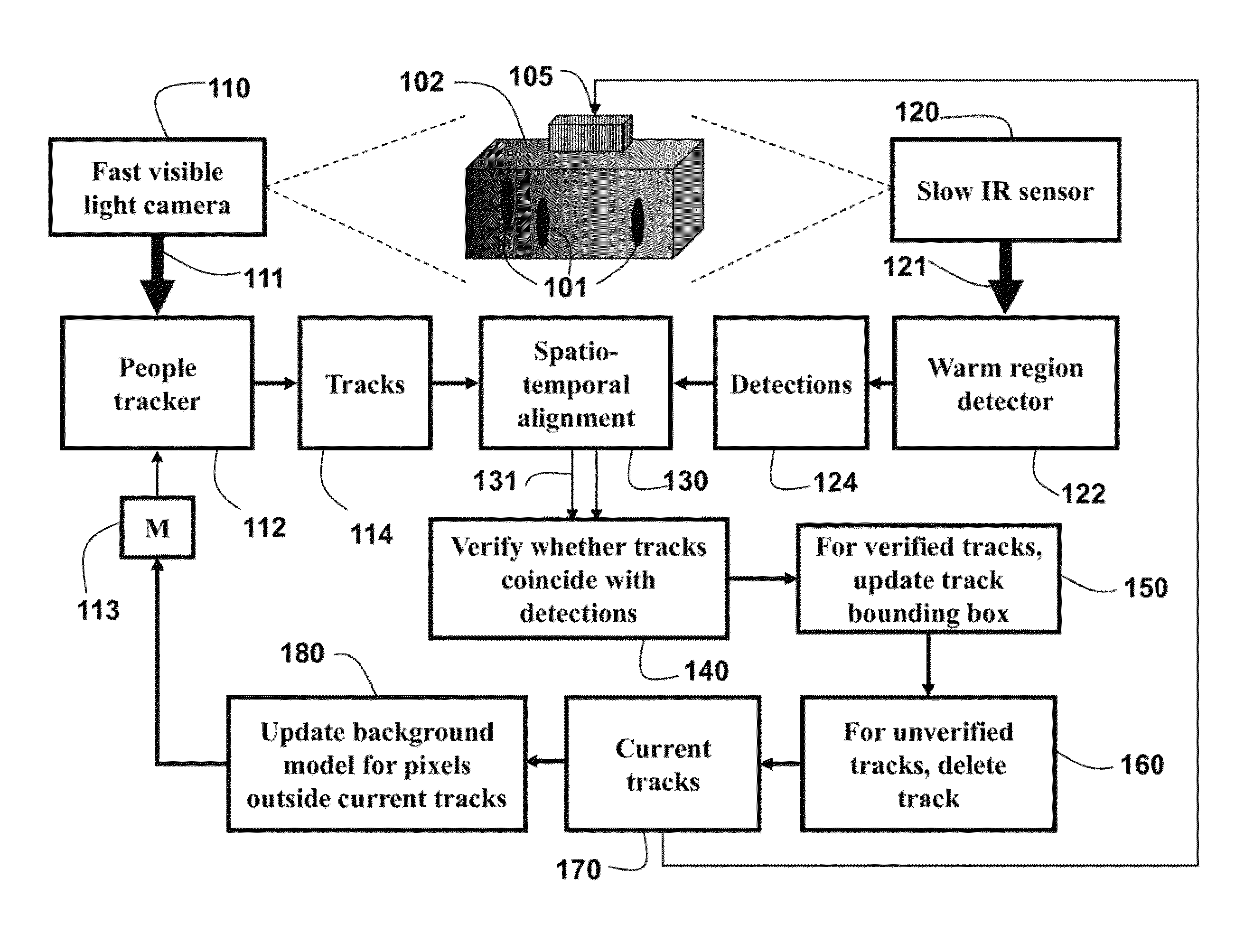
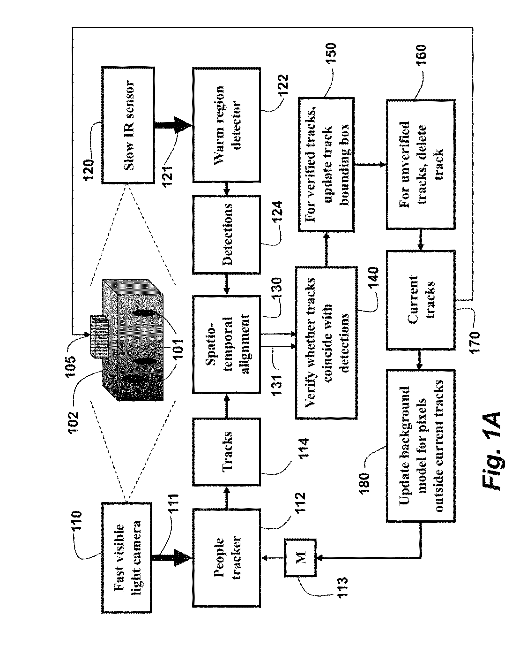
[0037]FIG. 1A shows a method and system for detecting and tracking people 101 in an environment 102 according to embodiments of our invention. A first sequence of images 111 of the environment is acquired by a visible-light (RGB) camera 110 having a first frame rate. A second sequence of images 121 of the environment is acquired by an infrared (IR) sensor 120 having a second frame rate. The second frame rate is substantially lower than the first frame rate. In some embodiments, the resolution of images from the IR sensor is much lower than the resolution of images from the RGB camera. In one embodiment, the thermal sensor includes an array of 32 thermal IR receivers arranged in a vertical line, which is partially rotated back and forth 200 by a motor in 94 discrete steps to produce a 140° field-of-view IR image over a time duration of one minute, see FIG. 2A. The RGB camera and the IR sensor are substantially colocated.

[0038]Objects, e.g., people, are tracked 112 in the first sequen...


PUM


Abstract

A method and system tracks objects in an environment by acquiring a first sequence of images of the environment with a visible-light camera having a first frame rate and a second sequence of images with a thermal infrared sensor having a second frame rate. The second frame rate is substantially lower than the first frame rate. The objects are tracked in the first sequence of images to obtain tracks. Warm regions in the second sequence of images are detected to obtain detections. The tracks and the detections are aligned spatially and temporally, and verified to determine whether the tracks and detections coincide after the aligning.

Description

FIELD OF THE INVENTION[0001]The field of the invention relates generally to computer vision, and more particularly to tracking people in a sequence of images online and in real-time.BACKGROUND OF THE INVENTION[0002]Person tracking is one of the fundamental problems in computer vision. There has been extensive work on tracking humans and other objects using visible-light video cameras, also referred to as red, green, blue (RGB) cameras. Despite much progress, human tracking remains a largely unsolved problem due to factors such as changing appearances, occlusions, motion of the camera and object, illumination variation, and background clutter. To deal with appearance ambiguities, a variety of methods exist that are based on techniques such as sparse representation, template selection and update, subspace-based tracking, and feature descriptors.[0003]A fundamentally different approach to appearance ambiguities is based on using multiple modalities of sensing. One option for multimodal...

Claims


Application Information

Patent Timeline
Patent Type & Authority Patents(United States)
IPC IPC(8): G06K9/46G06K9/52H04N5/33H04N7/18G01J5/02G01J5/00G06V10/143
CPCG06K9/46G01J5/0025G06K9/52H04N5/33H04N7/18G06T7/20G06T2207/10016G06T2207/10048G06T2207/20212G06T2207/30196G06V40/10G06V20/52G06V10/143
Inventor MARKS, TIMJONES, MICHAEL J.KUMAR, SUREN
Owner MITSUBISHI ELECTRIC RES LAB INC
Why Eureka
Try Eureka