Supercharge Your Innovation With Domain-Expert AI Agents!

Portable, temporary wall system

a temporary wall and portable technology, applied in the field of temporary wall systems, can solve the problems of flimsy and easily knocked, minimal privacy, and unsatisfactory commercial needs,

Active Publication Date: 2016-02-02
HOEFLER JAMES M
View PDF30 Cites 0 Cited by
  • Summary
  • Abstract
  • Description
  • Claims
  • Application Information

AI Technical Summary

Benefits of technology

This patent describes a wall system that has several technical benefits. Firstly, it can be easily adjusted without creating any holes or damaging the surrounding structures. Secondly, it is easy to assemble and disassemble even for people with no special building skills. Lastly, the wall system provides a stable and removable structure for dividing rooms. These technical characteristics make the wall system highly versatile and convenient for use in various building situations.

Problems solved by technology

However, currently available devices and / or methods include various disadvantages and drawbacks, leaving a variety of commercial needs which have not yet been met.
Although room divider screens may be easy to assemble and disassemble, and may include decreased cost, they also are often flimsy and easily knocked over while offering minimal privacy.
However, furniture can be heavy and difficult to move, expensive, include unfinished portions, and / or create substantial and potentially dangerous tip-over hazards.
However, stationary walls include significant drawbacks such as possibly requiring a building permit to erect, requiring expertise to construct, being difficult to remove, and leaving marks or holes in the floor, ceiling, and adjoining walls.
Additionally, stationary walls are often erected and dismantled in a manner that makes it difficult to reclaim the materials in a useable form.
Although pressurized walls provide a temporary solution without forming holes in the floor or ceiling, they also include various drawbacks.
Such drawbacks include potentially violating municipal building codes, being expensive to construct, and possibly requiring a contractor to dismantle the wall when no longer wanted, which may result in the contractor claiming the dismantled building materials.
When the contractor claims the dismantled building materials, the consumer not only pays for the contractor's time, but also realizes no equity in the original purchase of the pressurized wall.

Method used


Image

  • Portable, temporary wall system
  • Portable, temporary wall system
  • Portable, temporary wall system

Examples


example 1

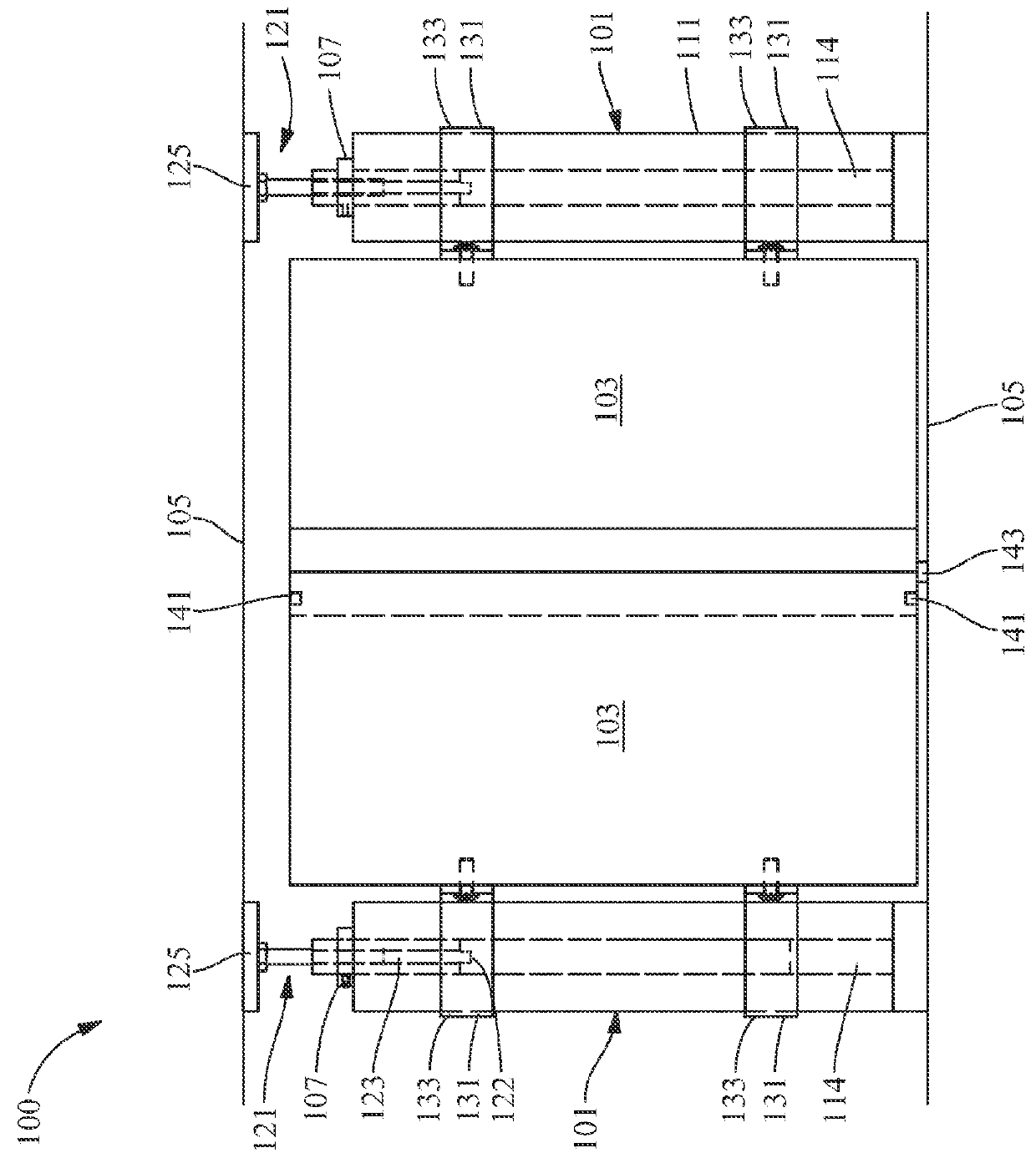
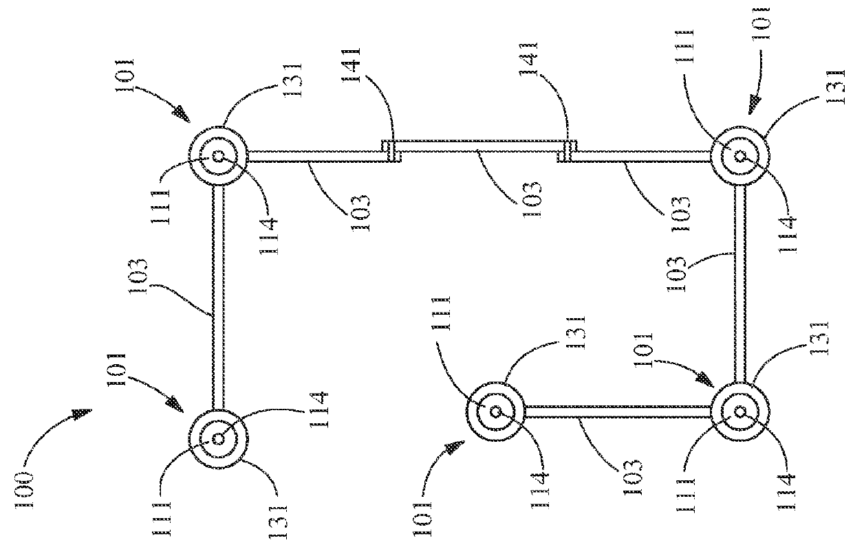
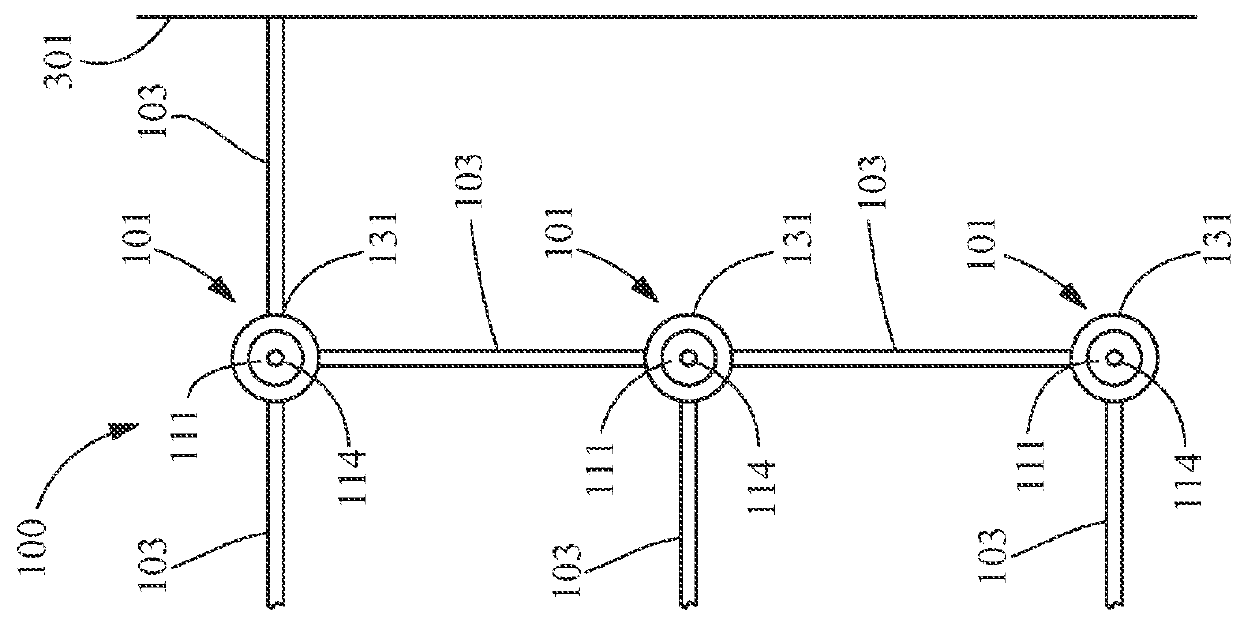
[0075]In one embodiment, the base portion 111 of the adjustable pillar member 101 includes a round tubular steel pole. The elongated member 123 of the expansion portion 121 includes a 1″ diameter steel pole formed in two sections 601, and configured to slide within the base portion 111. Assembly of the adjustable pillar member 101 includes attaching the base portion 111 to a base plate, rotating a 5′8″ threaded coupling in one of the two sections 601 along a ⅝″ threaded stud 604 to form the elongated member 123, and inserting the proximal end 122 of the elongated member 123 into the channel 114 forming the base portion 111. The expansion plate 125 is then secured to the distal end 124 of the elongated member 123.

[0076]After assembling the adjustable pillar member 101, the adjustable pillar member 101 is positioned between the opposing surfaces 105, which include the floor and the ceiling, and the expansion portion 121 is extended between the opposing surfaces 105. The locking member...

example 2

[0078]In one embodiment, the base portion 111 of the adjustable pillar member 101 is manufactured with engineered wood that is faced on both sides, then miter-folded. The miter-folding forms the channel 114, which includes a hollow section extending through the base portion 111. The hollow section formed by the miter-folding is cleaned of protruding materials (e.g., excess glue) to permit sliding of the expansion portion 121, which includes a metal expansion pipe, within the hollow section. The threaded metal inserts are inserted in columns on three consecutive sides 1411 of the base portion 111, each column including four threaded metal inserts for a total of twelve inserts per base portion 111.

[0079]After manufacturing and miter-folding the base portion 111, assembly of the adjustable pillar member 101 includes attaching the base plate to the base portion 111. The base plate includes a floor plate, which is a square plastic plate that sits on the floor. A bottom portion of the flo...


PUM


Abstract

The present invention relates to temporary wall systems and their production and more particularly to portable, temporary wall systems. The wall system includes an adjustable pillar member, a panel member, and a support article arranged and disposed to secure the panel member to the adjustable pillar member. The adjustable pillar member includes a base portion and an expansion portion, and is configured to extend between opposing surfaces to provide support for the panel member when secured thereto. The base portion includes a first face, an opposing second face, and a channel formed in the first face, the channel extending from the first face towards the second face. The expansion portion is movably disposed within the channel, and at least partially extends from the first face of the base portion.

Description

CROSS-REFERENCE TO RELATED APPLICATION[0001]The present application claims the benefit of and priority to U.S. Provisional Patent Application No. 61 / 940,632 entitled “PORTABLE, TEMPORARY WALL SYSTEM,” filed on Feb. 17, 2014, which is hereby incorporated by reference in its entirety.FIELD OF THE INVENTION[0002]The present application is directed toward the field of temporary wall systems and their production and more particularly to portable, temporary wall systems.BACKGROUND OF THE INVENTION[0003]Often, it is desirable to divide rooms into sections or sub-sections of an original configuration. For example, homeowners and apartment renters may wish to divide rooms in order to provide privacy, or make more efficient and creative use of the existing space. However, currently available devices and / or methods include various disadvantages and drawbacks, leaving a variety of commercial needs which have not yet been met.[0004]One currently available device includes a room divider, such as ...

Claims


Application Information

Patent Timeline
Patent Type & Authority Patents(United States)
IPC IPC(8): E04B2/74E04B2/82
CPCE04B2/7433E04B2/821E04B2002/749E04B2/7453E04B2002/7461E04B2002/7494
Inventor HOEFLER, JAMES, M.
Owner HOEFLER JAMES M
Features
  • R&D
  • Intellectual Property
  • Life Sciences
  • Materials
  • Tech Scout
  • Unparalleled Data Quality
  • Higher Quality Content
  • 60% Fewer Hallucinations
Learn More