Heavy duty ratchet

a ratchet and heavy-duty technology, applied in the field of ratches, can solve the problems of essentially limited tension force that can be applied, and achieve the effects of increasing the force on the entering cord, preventing slippage, and increasing the amount of force applied

Active Publication Date: 2016-02-09
KINGERY KENNETH G
View PDF19 Cites 3 Cited by
  • Summary
  • Abstract
  • Description
  • Claims
  • Application Information

AI Technical Summary

Benefits of technology

[0007]In a first embodiment of the invention, a housing supports a spool mounted on a shaft journalled within opposed sides of the housing. A pivotable pawl precludes rotation of the spool in one direction but upon pivoting the pawl against a spring bias, the spool is free to rotate. A cord enters the housing, extends partially about the spool and exits the housing. Upon pulling on the entering cord, tension will be applied to the exiting cord with commensurate rotation of the spool. Ridges on opposed sides of the spool interact with the cord to prevent slippage. To increase the amount of force applied to the spool and thereby the tension force on the entering cord, one or both ends of a shaft supporting the spool includes a socket for engagement by a tool. The additional leverage available from such tool, acts through the spool to further increase the force on the entering cord. In another embodiment of the invention, a hollow shaft supporting the spool includes an aperture disposed between the sides of the spool for inserting the entering cord and drawing it out through the end of the shaft. Once the entering cord is taut, a tool is inserted in a socket at the other end of the shaft to provide leverage for rotating the spool and wrap the cord about the spool to increase the tension on the entering cord. In a third embodiment of the ratchet, a lever is pivotally mounted within the housing about the shaft for the spool. A cord enters the housing and partially extends about the spool and thereafter exits the housing. An initial tension is applied to the entering cord by pulling on the exiting cord. Thereafter, repetitive angular movement of the lever results in commensurate rotation of the spool and the ridges on the spool interacting with the cord draws the entering cord about the spool to increase the tension. Reverse rotation of the spool is prevented by a pawl selectively releasable from engagement with the spool. In a variant of this embodiment, the cord enters a hollow shaft through a hole in the shaft and exits through one end of the shaft. Once the entering cord is tight by pulling on the exiting cord, the lever is repetitively angularly moved to wrap the entering cord upon itself within the spool and thereby significantly increase the tension on the entering cord.

Problems solved by technology

However, the amount of tension force that can be applied has been essentially limited by the degree of pulling force manually exerted upon the free end of the cord.

Method used


Image

  • Heavy duty ratchet
  • Heavy duty ratchet
  • Heavy duty ratchet

Examples


Embodiment Construction

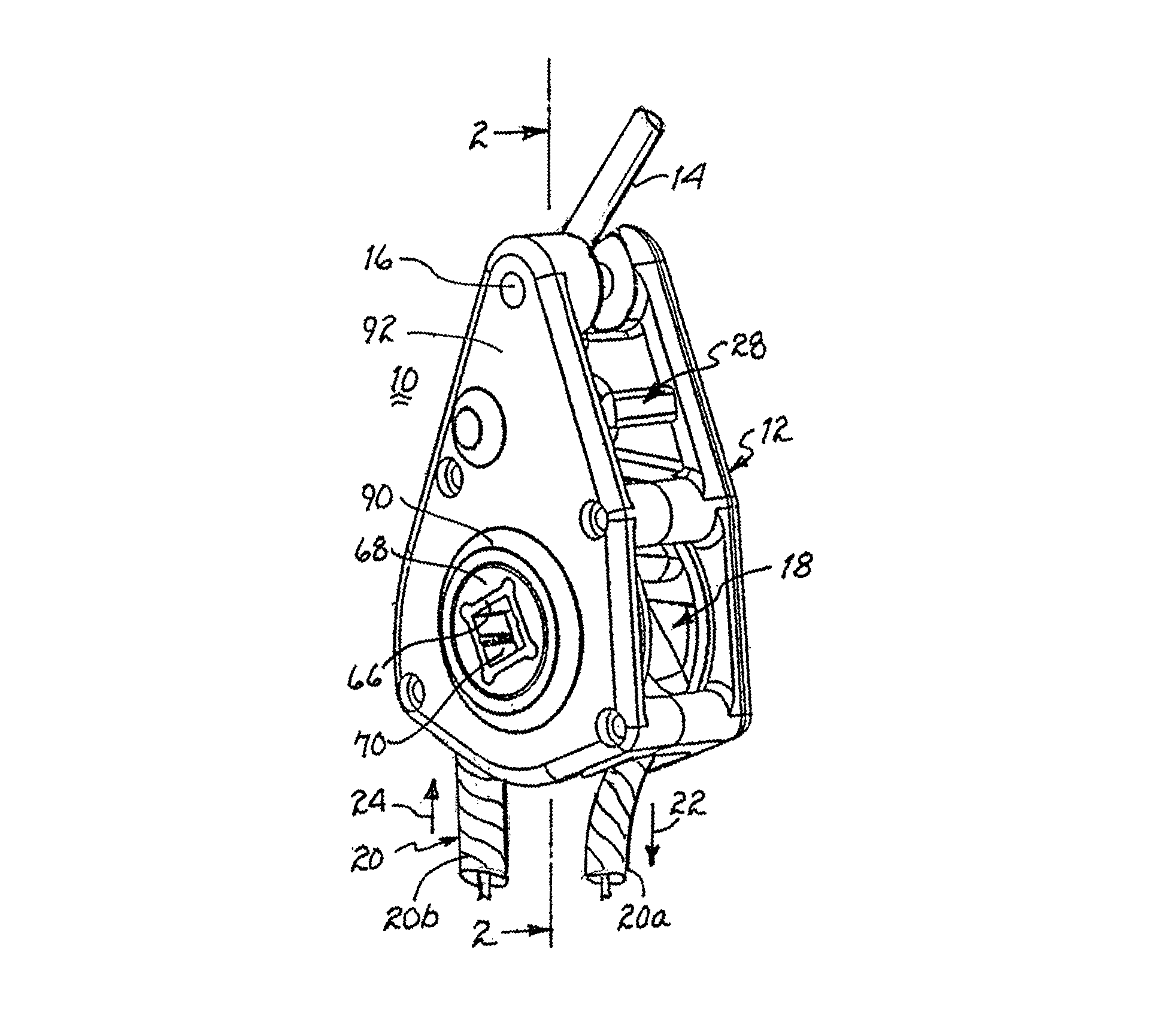
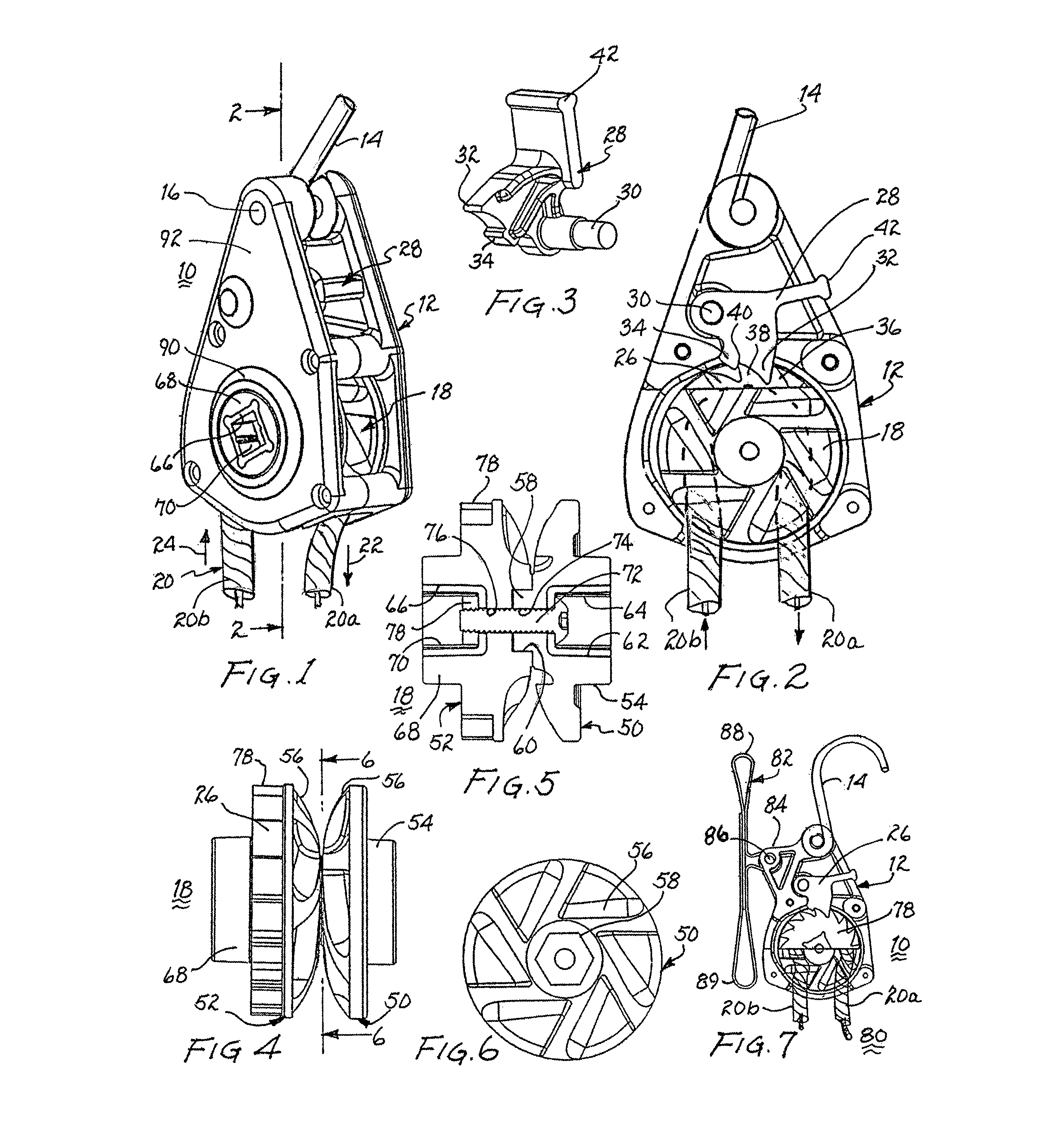
[0048]Referring to FIG. 1, there is shown a ratchet 10 defined in part by a housing 12. A cord or hook 14 is secured to the upper end of housing 12 by a shaft 16 lodged in the housing. A spool 18 is rotatably mounted within the housing. A cord 20, extends into housing 12 and partially encircles spool 18. Upon pulling on exiting cord 20a, as presented by arrow 22, entering cord 20b is drawn into housing 12, as presented by arrow 24 and about spool 18 and the spool will rotate commensurately.

[0049]FIG. 2 is a partial cutaway view of ratchet 10 and essentially taken along lines 2-2, as shown in FIG. 1. Spool 18 includes a ring of teeth 26. A pawl 28, as shown in FIGS. 2 and 3, is pivotally mounted within housing 12 on shaft 30. The pawl includes a primary prong 32 and a secondary prong 34. In operation, the primary prong nests in the triangular space between two adjacent teeth 36, 38 and secondary prong 34 extends past tip 40 of tooth 38. Thereby, pawl 28 prevents rotation of spool 18 ...


PUM

PropertyMeasurementUnit
diameteraaaaaaaaaa
tensionaaaaaaaaaa
circumferenceaaaaaaaaaa

Abstract

A ratchet includes a spool rotatably disposed within a housing and supporting a cord having opposed cord sections extending from the housing. Tension to one cord section is initially applied by pulling on the other cord section. To increase the tension, a tool is engaged with the spool to apply a further force to increase the tension on the one cord section. In another embodiment, a cord enters the housing and into the center of a hollow shaft supporting a spool and drawn through the hollow shaft to establish an initial degree of tension on the section of the cord entering the housing. A lever cooperating with the spool turns the spool to wrap the cord about the spool and increase the tension on the cord. In a third embodiment, a cord enters a housing and extends about a spool supported within the housing and thereafter exits the housing. A pivotable lever incrementally rotates the spool to increase the tension on the cord entering the housing. To further increase the tension on the spool, a wrench or the like may engage the shaft supporting the spool in any of the ratchets described.

Description

CROSS REFERENCE TO RELATED APPLICATIONS[0001]The present application claims priority to utility application entitled “TENSIONING ASSEMBLY”, assigned Ser. No. 13 / 653,647 and filed Oct. 17, 2012, and which claims priority to a provisional patent application entitled “TENSIONING ASSEMBLY”, assigned Ser. No. 61 / 548,140 and filed Oct. 17, 2011, both of which describe inventions made by the present inventor.BACKGROUND OF THE INVENTION[0002]1. Field of the Invention[0003]The present invention relates to ratchets and, more particularly, to heavy duty ratchets.[0004]2. Description of Related Prior Art[0005]Ratchets for use with cords of various types have been commercially available for a period of years. U.S. Pat. Nos. 6,068,242, 6,092,791, and Des. 362,614 are representative and are incorporated herein by reference. A ratchet of this type includes a housing having a hook or like member for attaching the ratchet to an anchor point. A spool within the housing supports a cord partially wrappe...

Claims


Application Information

Patent Timeline
Patent Type & Authority Patents(United States)
IPC IPC(8): B21F9/00B66D3/08B66D5/32B66D3/10B66F3/00
CPCB66D5/32B66D3/10
Inventor KINGERY, KENNETH, G.
Owner KINGERY KENNETH G
Why Eureka
Try Eureka