Method of testing secondary battery
a secondary battery and manufacturing technology, applied in sustainable manufacturing/processing, wound/folded electrode electrodes, instruments, etc., can solve the problems of short circuits that may occur in secondary batteries, so as to shorten the time taken for open circuit voltage to change due to ion diffusion, and reduce the non-uniformity of ion concentration
- Summary
- Abstract
- Description
- Claims
- Application Information
AI Technical Summary
Benefits of technology
Problems solved by technology
Method used
Image
Examples
embodiment 1
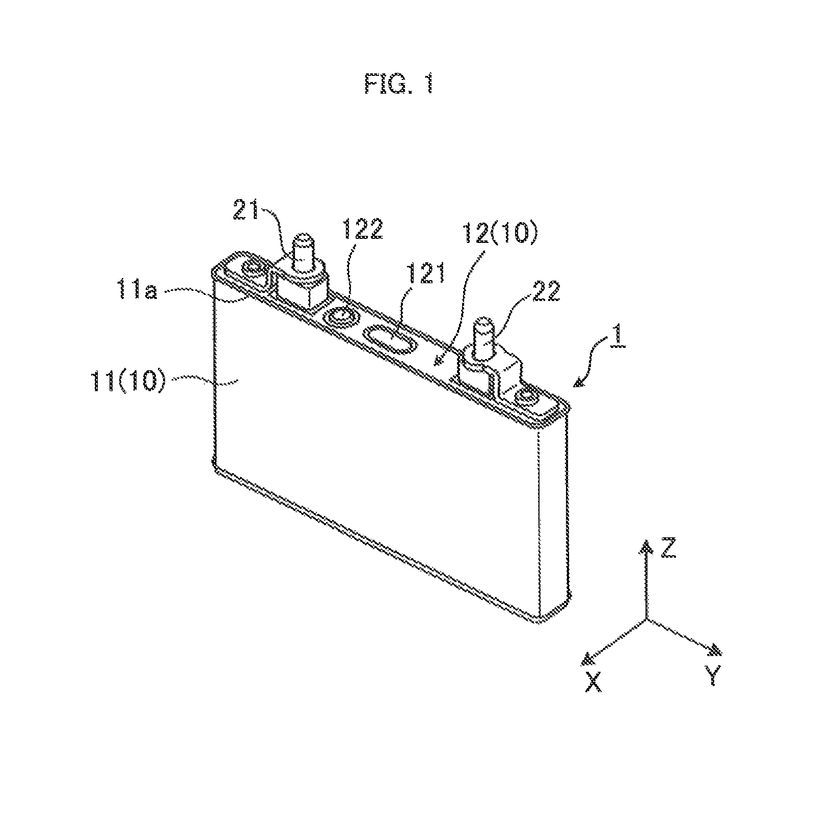
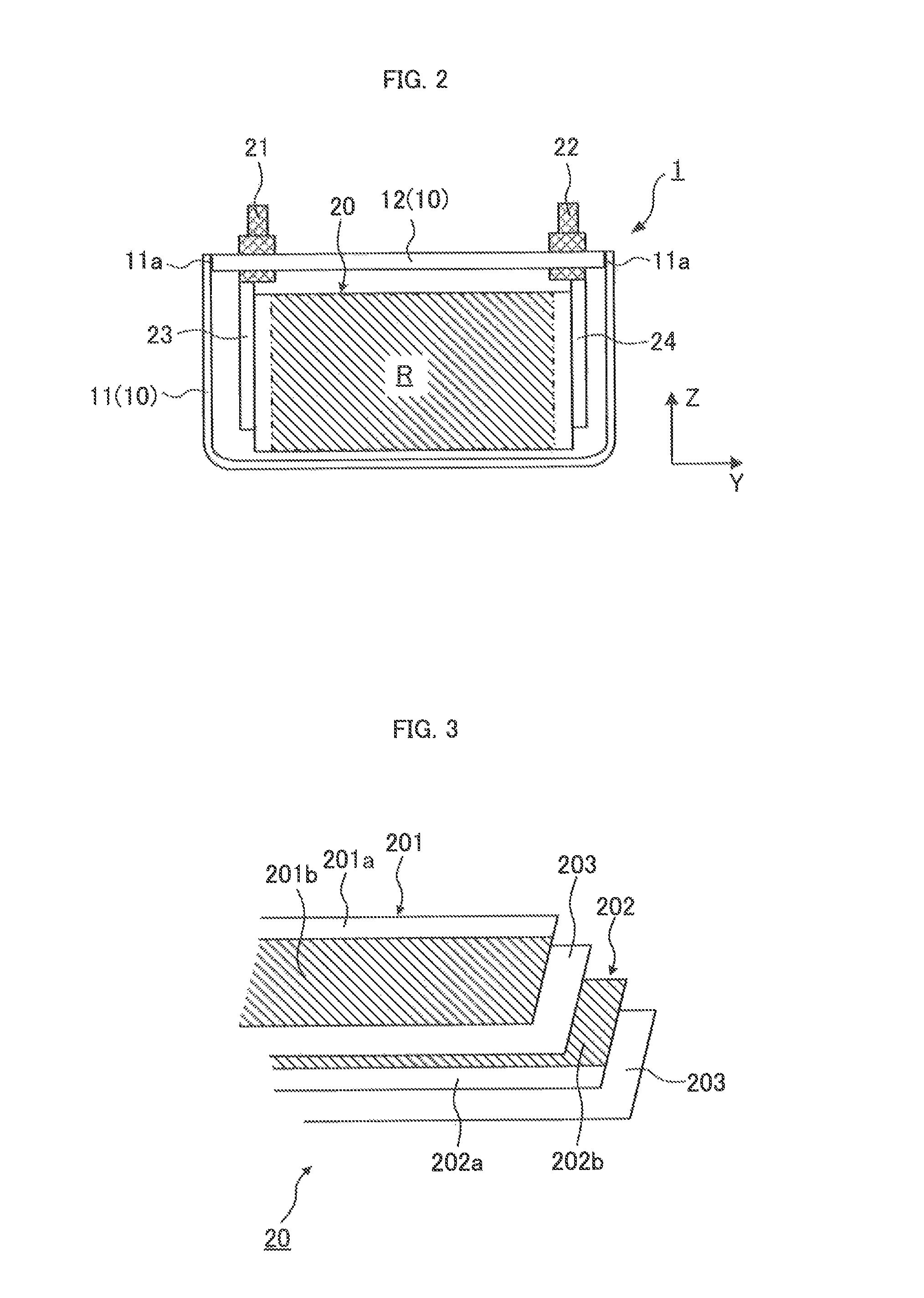
[0041]Description is made of the structure of a secondary battery which is Embodiment 1. FIG. 1 is an external view of the secondary battery which is Embodiment 1, and FIG. 2 is a diagram showing the internal structure of the secondary battery. In FIG. 1 and FIG. 2, an X axis, a Y axis, and a Z axis are axes orthogonal to each other. The relationship among the X axis, the Y axis, and the Z axis applies to the other figures.
[0042]Examples of the secondary battery 1 include a nickel metal hydride battery and a lithium-ion battery. The secondary battery 1 can be used as the power source for running of a vehicle.
[0043]Specifically, a plurality of secondary batteries 1 can be connected electrically in series to constitute an assembled battery, and the assembled battery can be mounted on the vehicle. An electric energy output from the assembled battery can be converted by a motor generator into a kinetic energy which can be used to run the vehicle. A kinetic energy generated in braking of...
embodiment 2
[0091]Description is made of a process of testing a secondary battery 1 which is Embodiment 2 of the present invention. The processing operations and members described in Embodiment 1 are designated with the same reference numerals, and detailed description thereof is omitted.
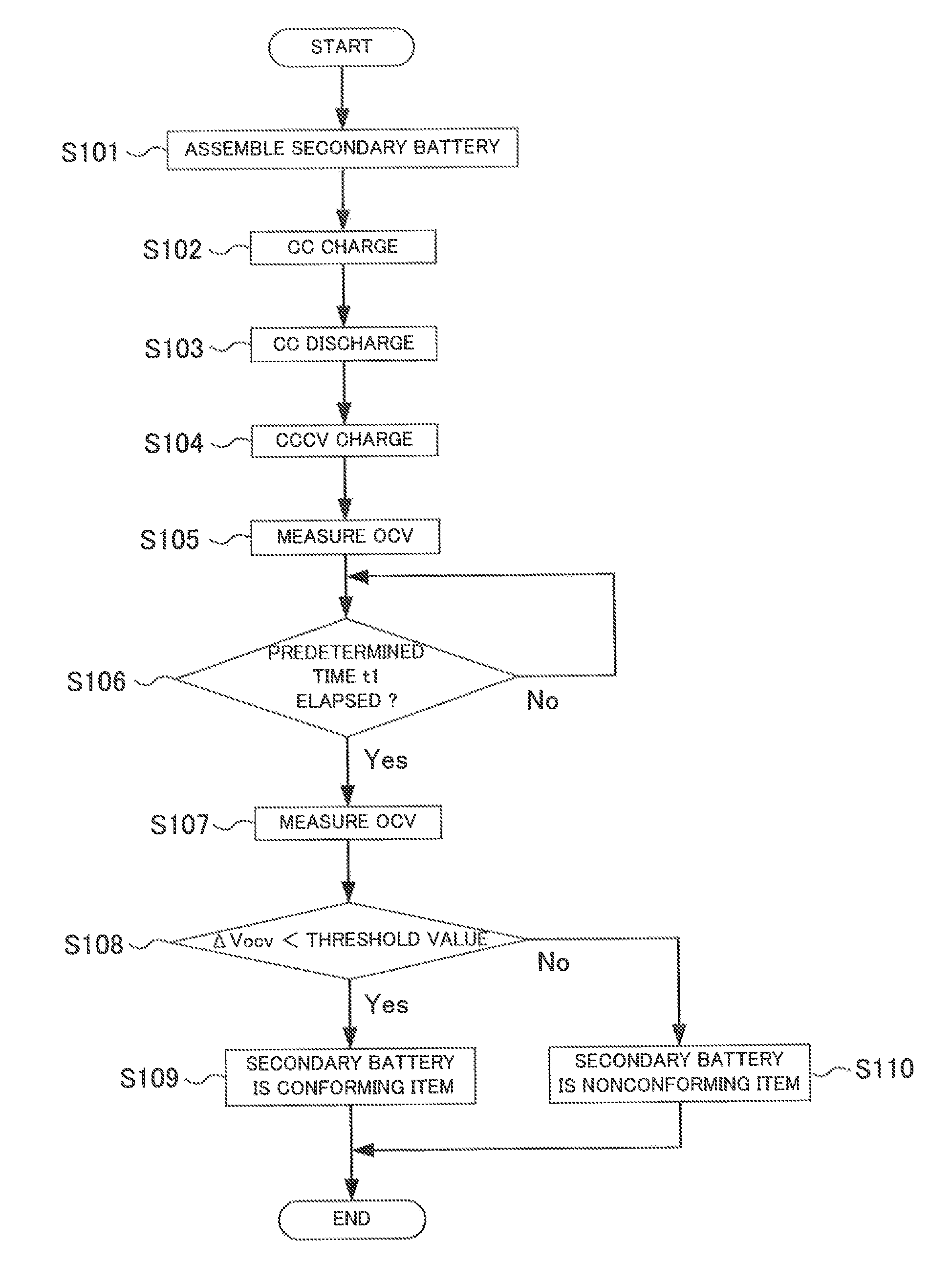
[0092]FIG. 14 is a flow chart showing the test process in the present embodiment. In Embodiment 1, the secondary battery 1 is assembled and then the charge in the CC mode is performed. In the present embodiment, however, the secondary battery 1 is assembled and then charge in the CCCV mode is performed at step S112. FIG. 15 is a graph showing changes in voltage of the secondary battery 1 when the test in the present embodiment is performed.
[0093]When the charge in the CCCV mode is performed, the voltage of the secondary battery 1 is increased to reach an upper limit voltage Vmax as shown in FIG. 15. After the voltage of the secondary battery 1 reaches the upper limit voltage Vmax, the voltage of the secondary b...
embodiment 3
[0101]Description is made of a process of testing a secondary battery 1 which is Embodiment 3 of the present invention. The processing operations and members described in Embodiment 1 are designated with the same reference numerals, and detailed description thereof is omitted.
[0102]In the present embodiment, after processing at step S102 (charge in the CC mode) is performed, discharge in the CCCV mode is performed at step S113. FIG. 21 shows changes in voltage of the secondary battery 1 when the test in the present embodiment is performed. The discharge in the CCCV mode causes the voltage of the secondary battery 1 to be reduced from the upper limit voltage Vmax and to reach the target voltage Vt. When the voltage of the secondary battery 1 reaches the target voltage Vt, discharge is performed at a constant voltage to maintain the voltage of the secondary battery 1 at the target voltage Vt.
[0103]When the processing at step S113 is performed, the ion concentration at the first interf...
PUM
| Property | Measurement | Unit |
|---|---|---|
| voltage | aaaaa | aaaaa |
| constant-current constant-voltage | aaaaa | aaaaa |
| open circuit voltage | aaaaa | aaaaa |
Abstract
Description
Claims
Application Information
 - R&D
- Intellectual Property
- Life Sciences
- Materials
- Tech Scout
- Unparalleled Data Quality
- Higher Quality Content
- 60% Fewer Hallucinations
Browse by: Latest US Patents, China's latest patents, Technical Efficacy Thesaurus, Application Domain, Technology Topic, Popular Technical Reports.
© 2025 PatSnap. All rights reserved.Legal|Privacy policy|Modern Slavery Act Transparency Statement|Sitemap|About US| Contact US: help@patsnap.com


